When you combine raster and vector data in a single drawing you must set the image insertion parameters appropriately.
- it may be difficult to know the required parameters before you actually insert the image into the current drawing
- but you can insert an image with default parameters & then use Move, Scale & Rotate commands to align images to vectors.
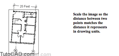
An effective way to align images with drawings is to use the Reference option of Scale & Rotate.
- you must know the distance (in drawing units) between 2 points in the image.
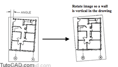
- similarly, you should know an angle (normally a vertical or horizontal scanned line) for a feature in the image file.
PRACTICE ALIGNING IMAGES WITH VECTOR DRAWINGS
1) Close the drawing from the previous exercise if it is open.
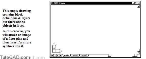
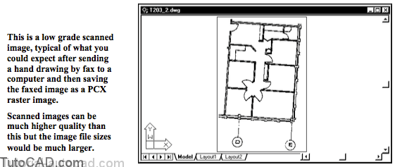
2) Open the T203_2.dwg drawing in your personal folder.
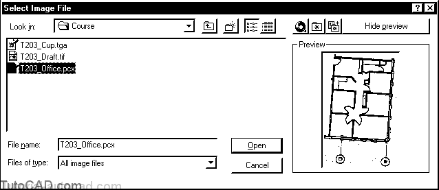
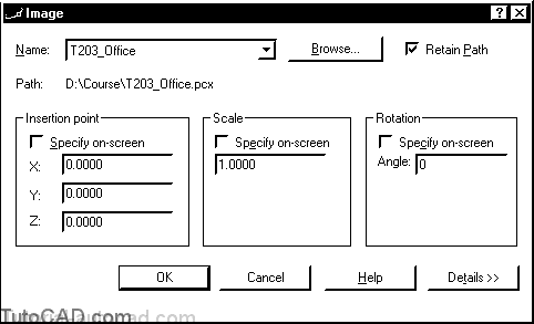
3) Pick Insert + Raster Image. Select the T203_Office.pcx file and pick Open to continue.
4) Uncheck all Specify on-screen boxes and pick OK.
5) Pick View + Zoom + Extents to see the attached image.
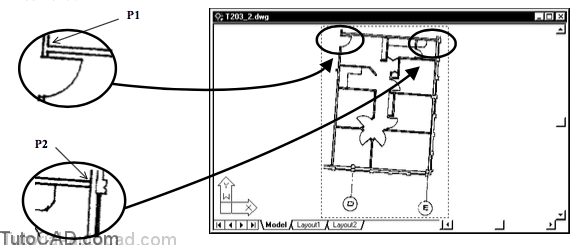
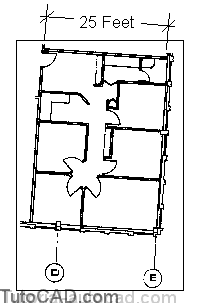
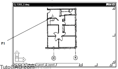
6) Pick Modify + Scale. Select the image frame when prompted to select objects then press <enter> to continue. Follow the dialogue below to scale the image such that the distance between points P1 & P2 is 300 (25 feet).
Command: SCALE↵
Select objects: (picktheimageframe)
Select objects: ↵
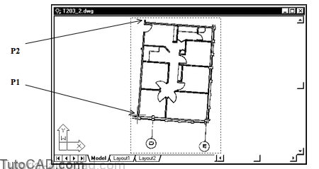
Specify base point: (pickinsidecornerpointnearP1)
Specify scale factor or [Reference]: R↵
Specify reference length <1>: (pickinsidecornerpointagainnearP1)
Specify second point: (pickinsidecornerpointnearP2)
Specify new length: 300↵
Command:
You can Zoom in transparently to pick these points more precisely if you wish but in this exercise it is not critical to be precise.
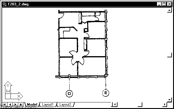
7) Pick View + Zoom + Extents.
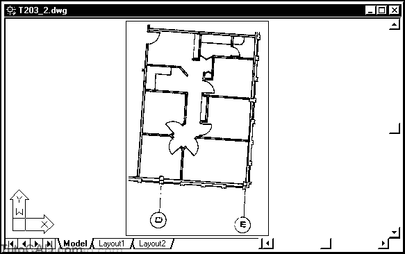
The image will look the same on your screen but if you performed the last step properly it should now be inserted at the desired scale.
- the inside dimension shown below should be 300 drawing units (inches) which corresponds to 25 feet.
- you could use the Dist command to verify that the distance between these points in the image is approximately correct.
In the next step you will use the Reference option of Rotate to align the image walls with vertical & horizontal directions in AutoCAD.
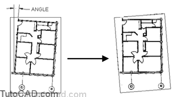
8) Pick Modify + Rotate and select the image frame when AutoCAD prompts to select objects then press <enter> to continue. Follow the dialogue below to align the image walls to vertical and horizontal directions.
Command: ROTATE↵
Current positive angle in UCS: ANGDIR=counterclockwise ANGBASE=0 Select objects: (picktheimageframe)
Select objects: ↵
Specify base point: (pick point along outside edge of wall near P1)
Specify rotation angle or [Reference]: R↵
Specify the reference angle <0>: (pick the same point P1)
Specify second point: (pick another point along the outside of the wall near P2)
Specify the new angle: 90 ↵
Command:
9)Pick Modify + Object + Image + Frame. Then right-click in the drawing area to invoke a shortcut and select OFF.
The image is now aligned with the vector drawing so you could now insert furniture symbols at a scale of 1 in this drawing.
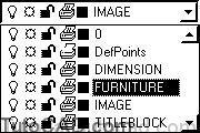
10) Make FURNITURE the current layer.
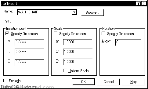
11) Pick Insert + Block. Select WAIT_CHAIR as the name and check Specify on-screen for Insertion point. Uncheck Specify On-screen for Scale & Rotation. Pick OK to continue.
12) Move your crosshairs near P1 below and left-click to use this as the insertion point for this chair.
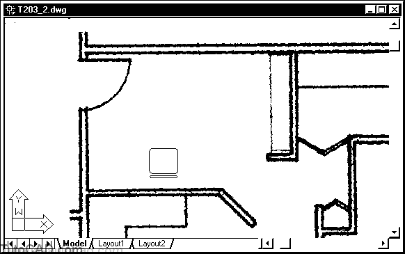
13) Pick View + Zoom + Window and zoom into the room that you just inserted the chair in so that this room almost fills your screen.
When you Zoom in you can see clearly the difference between this low grade raster image and the (vector) chair symbol
- but with higher quality raster images (with much larger file sizes) it would not be obvious on your screen or in final plots.
You can use add-on applications (e.g. Autodesk CAD Overlay 2000) to convert a raster image into an equivalent vector drawing.
- a collection of pixels that appear to be in a straight line could generate an equivalent vector LINE object.
- a collection of pixels that appear to be in a circular form could generate an equivalent vector CIRCLE object, etc..
You may have to experiment to yield a suitable drawing that matches a raster image
- but the advantage of being able to edit the resulting vector objects may be well worth your effort
- file sizes are much smaller and it would be much easier than manually redrawing an entire image using vectors in AutoCAD.
14) Save the changes to the current drawing and Close the file.