Dimensioning The Layout 3D
Create dimensions in the Model (you will see MODEL in the status bar) from the Layout tab.
- the UCS saved with each viewport is normally parallel to the view when you create drawings using default settings.
- you would have to use the View option of Ucs if for some reason the current UCS in the current viewport is not parallel to the view.
- if there is not enough room for dimensions you can use grip editing techniques to change viewport sizes on the Layout tab.
You must change the current Layer to be the [viewname]-DIM layer that Solview automatically created for the current viewport.
- for example, if you were creating a dimension for the Front viewport you would make Front-DIM the current Layer.
- it is easier to change the current layer for each viewport if you create Named Layer Filters for dimension layers.
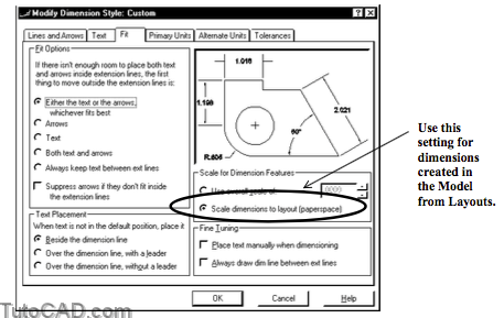
It is practical to Scale dimensions to layout (paperspace) in your dimension styles because you create dimensions on a Layout tab.
- then you can use the same dimension styles for all drawing scales (no need to change DIMSCALE for different drawings).
- you should also lock the view magnification for all viewports when you use this feature.
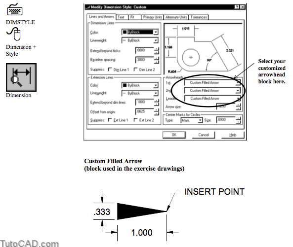
Arrowheads of dimensions created in a UCS other than the World may display & plot hollow (not filled) in your drawings.
- the first release of AutoCAD 2000 exhibited this behavior but this problem may be eliminated in future releases.
Dimension styles in the exercise drawings have been modified to use a special arrow head block to avoid this problem.
- you can create your own arrow head block with a HATCH object instead of the 2D SOLID normally used for arrowheads.
- then select your customized arrowhead block for the dimension style used to dimension your SOLID models.
PRACTICE ADDING DIMENSIONS
» 1) Open the T305_6.dwg file in your personal folder (or open the drawing from the last exercise).
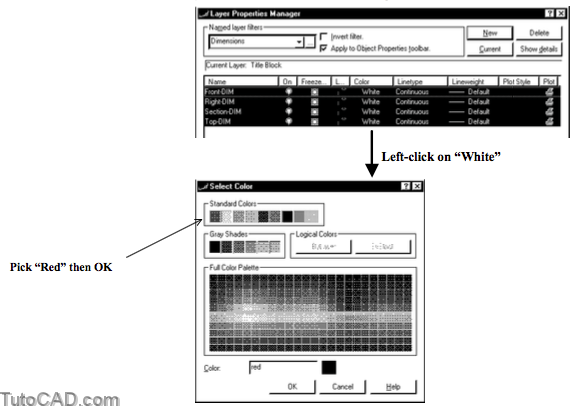
» 2) Pick Format + Layer. Pick the button to invoke the Named Layer Filters box. Type Dimensions as the Filter name and type *DIM as the Layer name. Pick Add then Close to return to the Layer dialogue box. Select the new Dimensions Named layer filter to list only the dimension layers and make sure that Apply to Object Properties toolbar is checked before you continue.
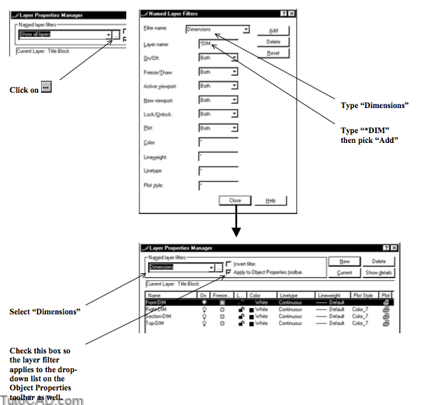
3) Select all 4 dimension layers then left-click on the White color for one of these layers to invoke the Select Colors box. Select Red then pick OK to return to the main box and pick OK to terminate the Layer command.
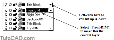
4) Left-click on the arrow in the Layer control drop-down list and left-click on Front-DIM layer to make it current. Then left-click on the arrow to roll up the list again.
The Title Block layer was current before the last step so this layer was listed with the other layers matching the Dimensions filter.
- now that Front-DIM is current you will only see the four dimension layers in this drop-down list.
- it will be easier to select an appropriate layer (using this filter) before you create dimensions in one of the viewports.
5) Make sure you can see PAPER in the status bar (left-click on MODEL if that button appears in the status bar instead).
6) Select the Front viewport to display the grips in each corner. Then left-click in the upper right corner grip near P1 to make it hot. Move your crosshairs and left-click near P2 to Stretch the viewport to the new size. Press <Esc> twice to clear the grips.
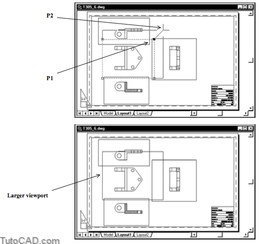
You can use this grip editing technique to change the size of viewports as required to make room for dimensions.
- the 2D geometry remains in the same location on the layout.
- you do NOT change the view magnification scale.
You can also Move the VIEWPORT objects on the Layout but you should use the POLAR tool to move them in orthogonal directions then you will not have to worry about re-aligning viewports later on
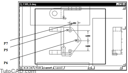
7) Pick View + Zoom + Window and zoom into the Front viewport so that it almost fills your screen as shown below.
8) Double-click inside the Front viewport to switch to the MODEL and make this the current viewport.
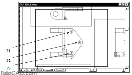
9) Pick Dimension + Center Mark and select the CIRCLE near P1. Repeat for the other CIRCLEs near P2 & P3.
10) Make sure OSNAP is ON in the status bar.
11) Pick Dimension + Linear. Use Endpoint osnaps for the top ends of the center marks near P5 & P6 then pick near P7 to create the 1.500 horizontal dimension shown. Use a similar technique to create the other 2.000 dimensions shown.
12) Pick View + Zoom + Extents to see the entire title block area again. (the viewport display should be locked!)
13) Left-click in the Top view to make it current.
14) Pick View + Zoom + Window and zoom in so this viewalmost fills the screen. (this viewport should be locked too).
» 15) Select the Top-DIM layer in the Layer control drop-down list of the Object Properties toolbar to make it the current layer.
» 16) Pick Dimension + Radius. Pick the ARC near P1 then pick near P2 to create the radial dimension shown.

More practice?
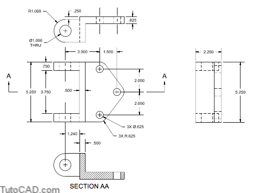
17) Add more dimensions in the other viewports using a similar process (the illustration below is a guideline only).
18) Save the changes to your drawing and Close the file.