Orthographic Views
Most drafters are familiar with the concept of a “glass box” to help generate 2D orthographic views of 3D objects.
- imagine your object inside a rectangular glass box and the 2D views used for drafting are projected to the faces of this box.

- then imagine unfolding these faces onto a flat plane (the sheet of drafting paper) to generate a 2D drawing.
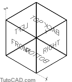
2D drawings normally include only two or three views but there are a total of 6 orthographic views to choose from.
- you can completely unfold the “glass box” to lay out all 6 orthographic views properly in a 2D drawing.
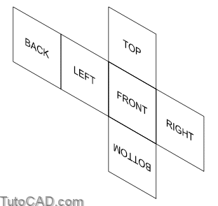
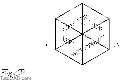
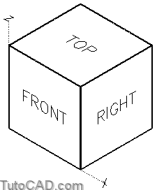
The illustration below shows these standard orthographic views and the labels illustrate the default orientation in AutoCAD.
- when you view one of these six views you would see the text label such that it reads properly on-screen (from left to right).
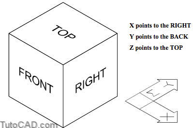
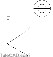
The illustration below shows the relationship of these orthographic views to the World Coordinate System (WCS) axes in AutoCAD.
You will also want to view models from isometric viewing directions.
- this is a common viewing direction for illustrations because you can see most (if not all) model features in one view.
- it is also practical to create models from this viewing direction because it exposes more edges and object snaps.
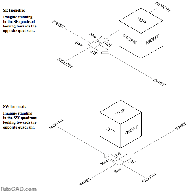
AutoCAD uses quadrants based on compass directions (North, East, West & South) to abbreviate isometric viewing directions.
- East represents the X axis direction and North represents the Y axis direction.
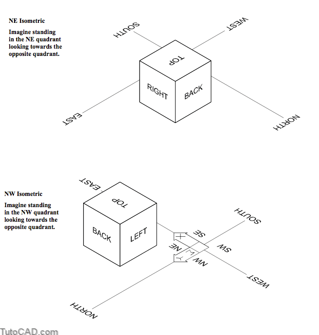
Standard isometric views are from above so you would not see the bottom of your models after Hide (or in Hidden & Shaded modes).
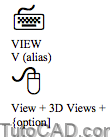
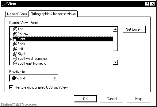
You can change your viewing direction to display one of the 6 orthographic views or 4 isometric views using the View command.
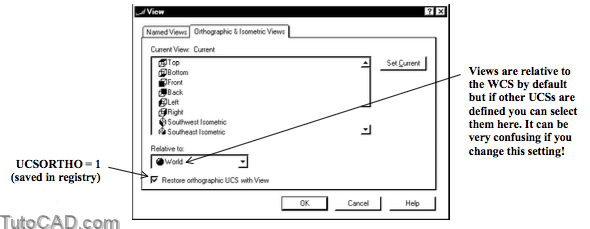
- if you invoke the View dialogue box you can select the desired view on the Orthographic & Isometric Views tab.
- double-click on the desired view to make it Current (or select the desired view and pick Set Current) then pick OK.
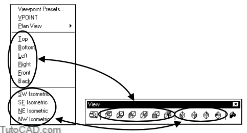
Use the View toolbar buttons or View + 3D Views pulldown menus to restore views directly (you do not invoke the View dialogue box).
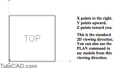
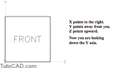
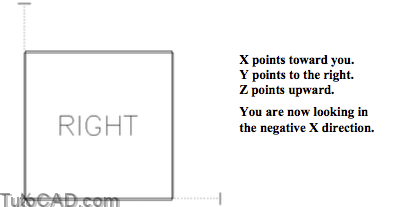
When you display an orthographic view AutoCAD may automatically change the current UCS to align with that view, such that
- the X axis points to the right, the Y axis points up and the Z axis points directly at you out of the screen.
- if you do not want to change the UCS you can uncheck the Restore orthographic UCS with View setting in the View box.
So far you have learned how to use the View command to change your viewing direction for standard views.
- there are other tools/commands to achieve similar results but they can also be used to set non-standard viewing directions.
These other tools/commands are somewhat obsolete in AutoCAD 2000 because of the new 3dorbit command.
- you will be learning how to use the new intuitive 3dorbit command in the next section of this document.
You can specify viewpoint vectors using the Vpoint command.
- for example, 1,1,1 is the vector for NE Isometric & you could use1,1,–1 to look at your model from below.
- if you press <enter> at the main prompt instead of entering a vector you can drag the vector dynamically using a tripod.
You can specify the viewing direction by changing two different angles using the ddVpoint command.
- this can be useful when edges overlap in isometric views (a common problem in mechanical parts).
- you can alter viewing angles slightly (from the standard angles) to expose more edges in non-standard isometric views.
PRACTICE WITH STANDARD VIEWING DIRECTIONS
» 1) Close the drawing from the previous exercise if it is open.
» 2) Open the T302_2.dwg drawing in your personal folder.
3) Pick View + Shade + Hidden to change the shademode.
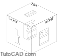
This is a simple 3D model of a box and you are currently viewing the model from the SW Isometric viewing direction.
- each face on this box has a TEXT object with the corresponding orthographic view name for that face.
- with shade mode set to Hidden you see only the TEXT labels on faces that have their outside surface oriented towards you.
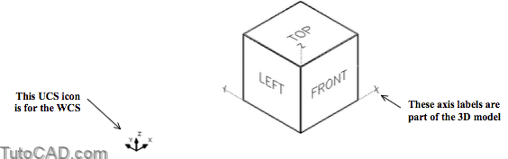
The X, Y and Z axes of the World Coordinate System (WCS) are also labeled on this model
- at the moment the current UCS is the WCS so the UCS icon matches the XYZ axes that are part of the 3D model.
It can be confusing when you restore orthographic views and the UCS changes to align itself with the new view.
- so in the next step you will turn UCSICON Off.
» 4) Pick View + Display + UCS Icon + On (toggles check Off).
» 5) Pick View + 3D Views + Top.
6) Enter V (as an alias) at the keyboard to invoke the View dialogue box. On the Orthographic & Isometric Views tab select Front and pick the Set Current button. Then pick OK.
7) Display the View toolbar (if it is not already displayed). Pick the Right View button to view the model from the right side.

You have used the View command to change your viewing direction three times but you invoked View differently each time.
- you can use the View dialogue box
- or you can avoid the View dialogue box by selecting a menu option (pulldown menu or toolbar button).
When you change your viewing direction AutoCAD displays the current drawing extents to fit in the active viewport.
- you can always Zoom in for magnified views after setting a new viewing direction.
» 8) Pick View + 3D Views + SE Isometric.
If you were to stand in the SE quadrant (positive X but negative Y) and look toward the opposite quadrant this is what you would see.
- the SE Isometric & SW Isometric viewing directions are practical for illustrations and presentations.
More practice?
» 9) Pick View + Shade + 3D Wireframe.
When you view models in standard isometric viewing directions, some edges and intersection points may overlap.
- this can make it difficult to select snap points or select the desired edges in commands.
- you can change angles slightly to overcome this problem.
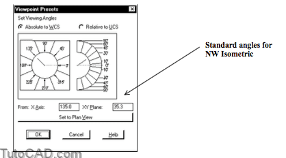
10) Pick View + 3D Views + Viewpoint Presets. Change the angle From X Axis to 300 (was 315) and the angle From XY Plane to 30 (was 35.3). Then pick OK.
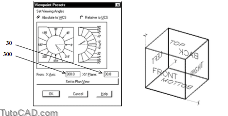
Now each vertex of this box is clearly visible and you can identify all individual edges (even at the back of the model).
- this non-standard isometric viewing direction can be practical for creating and editing 3D models.
» 11) Practice viewing various standard isometric viewing directions. Imagine what the view should look like before you change viewing directions and then see if you were right.
Still more practice?
» 12) Close the current drawing without saving changes.
» 13) Open the T302_3.dwg drawing in your personal folder.
» 14) Using methods of your choice view this model from the Top, Front and then from the Right side.
You may want to Zoom Out after changing view directions because the extents in this drawing are the same size as the model.
» 15) Using the method of your choice view this model from the NE Isometric viewing direction.
» 16) Change the shade mode to Gouraud Shaded.
» 17) Close this drawing without saving any changes.