Polar Tracking & Direct Distance Entry
Polar Tracking is new in AutoCAD 2000 and it can be used as an alternative to how Ortho was used in earlier AutoCAD Releases.
Polar Tracking is On if the POLAR status bar button is pushed in(you can toggle this setting while a command is running).
- if Polar Tracking is On you can imply Ortho constraints using your crosshairs when AutoCAD prompts for a second point.
- hold your crosshairs approximately in an orthogonal direction and you will see a Tooltip and a Polar Tracking vector appear.
- the Aperture Size on the Drafting tab of Options controls how close you must be to a precise ortho direction.
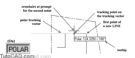
When you see the Polar Tooltip appear you can move your crosshairs (approximately) along the polar tracking vector.
- you will see a small tracking point (it looks like an “x”) on the tracking vector that moves as you move your crosshairs.
- the tracking point is used as the second point if you left-click with your mouse.
Ortho still functions the same way as in earlier AutoCAD releases
- but you cannot have both ORTHO and POLAR status bar buttons pushed in (On) at the same time
- once you are familiar with the Polar Tracking tool you may prefer to always leave Ortho Off.
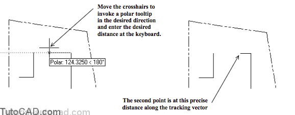
Polar Tracking can be used with direct distance entry techniques for points at precise distances along the tracking vector.
- move your cursor to invoke a Polar Tooltip for the desired direction and enter the desired distance at the keyboard.
Command: _line Specify first point: (pick first point)
Specify next point or [Undo]: 60 ↵(enter distance when you see desired polar tooltip)
Specify next point or [Undo]: ↵
Command:
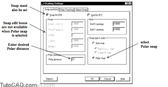
If your drawings use repeatable distances you can use Polar snaps as an alternative to direct distance entry methods.
- change Snap type & style to Polar snap & enter a Polar distance in the Snap and Grid tab of Dsettngs.
- this approach is more practical to the Grid snap Snap settings because these snap points are relative to your last point.
When you use the Polar snap approach you can supply precise points without need for additional keyboard activity or menu picks.
Even if your drawings do not use predictable distances it can still be a good idea to set up your drafting tools to use Polar snaps.
- if the desired distance ends up being a multiple of the polar distance (increment) then you can use the snap point.
- otherwise, use direct distance entry to override the distance of a snap point while still using the polar tracking vector direction.
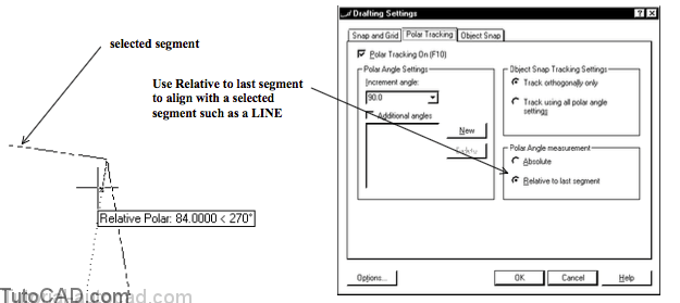
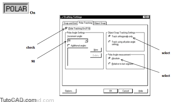
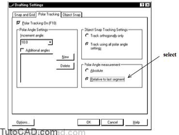
Polar Tracking can also be set to use either relative or absolute angle measurement in the Polar Tracking tab of Dsettings.
- in Absolute mode the tracking vector will be relative to the X axis of the current UCS.
- in Relative to last segment mode the tracking vector will be aligned relative to a selected segment.
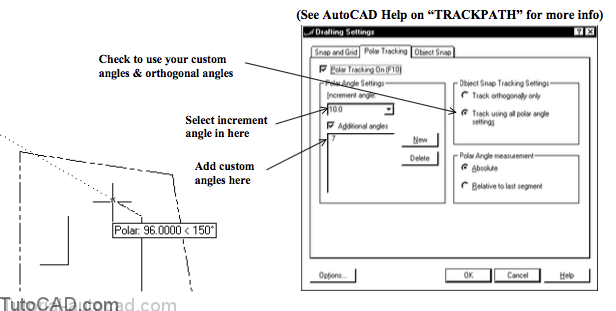
The default increment angle is 90 degrees but you can select other standard angles & add custom angles to the list.
- then you can decide whether to Track orthogonally only or to Track using all polar angle settings.
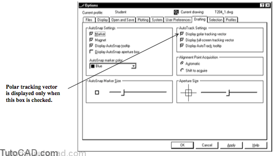
You should also consider how the Drafting tab settings in Options can effect Polar Tracking
- if you do not want to see a Polar Tracking vector you can turn this setting off in this dialogue box.
PRACTICE USING POLAR TRACKING & DIRECT DISTANCE ENTRY
»1) Close the drawing from the previous exercise if it is open.
»2) Open the T204_2.dwg drawing in your personal folder.
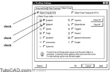
»3) Right-click on the OSNAP status bar button and select Settings from the shortcut. Check only Object SNap On, Endpoint & Midpoint osnaps (all other boxes should be unchecked). Then pick the Polar Tracking tab to continue.
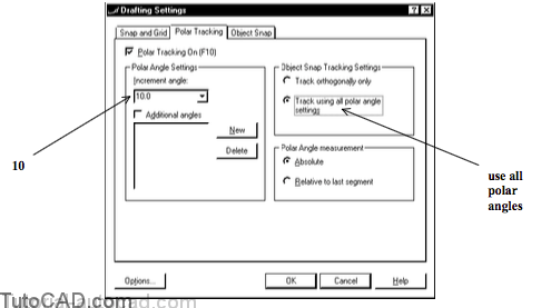
4) Check Polar Tracking On and verify that the other settings match those shown below. Pick OK to close the box.
5) Make FOUNDATION the current Layer.
![]()
6) Pick Draw + Line and move your crosshairs to the end of the LINE near P1 until you see the Endpoint marker and then left-click to use this point.
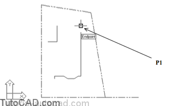
7) Hold your cursor near the points shown below (without pressing your left mouse button) and observe the Polar Tracking vector and Tooltips for each point. Do not pick any of these points.

The Polar Angle Setting currently uses 90 for the increment angle
- so your crosshairs can be constrained in the same directions as if you turned Ortho On (like in earlier AutoCAD releases).
- the ORTHO status bar button is Off right now.
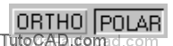
8) Left-click on the ORTHO status bar button and move your crosshairs around again at the prompt to Specify next point without picking any points.
If ORTHO is On there are no Polar Tooltips or Tracking Vectors.
The POLAR status bar button popped out automatically when youpushed in the ORTHO status bar button.
- ORTHO and POLAR cannot both be On at the same time.

The POLAR settings that you have set now would be similar to what ORTHO could do for you in earlier AutoCAD releases
- so you should consider always having ORTHO Off and working with POLAR On instead
- and you would have the advantage of many more useful features that you are about to work with in the remainder of the exercise.
You have been changing many different drafting settings since you began the Line command several steps ago
- and the Line command is patiently waiting for you to continue using it once you decide how to set your drafting settings.
» 9) Left-click on the POLAR button to toggle it On again. The ORTHO tool will toggle Off automatically.
10) Right-click on POLAR & select Settings from the shortcut. Change the Increment angle to 10 and select Track using all polar angle settings. Then pick OK to continue with Line.
11) Move your crosshairs until you see a Polar tooltip for 150 degrees (15 multiples of the current 10 degree increment) and then enter a distance of 48 at the keyboard.
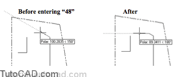
You just used the direct distance entry method to create a new LINE that is 48 drawing units (4 feet) in a 150 degree direction.
» 12) Right-click on the SNAP status bar button and select Settings from the shortcut menu.
When you right-click on a drafting setting toolbar button & then pick Settings you go directly to the appropriate tab of Dsettings.
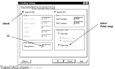
13) Check the Snap On box and select Polar snap for the Snap type & style and then enter 12 as the Polar distance. Pick OK to return to Line.
You selected Polar Snap as the Snap type & style & SNAP is On
- so now when you are prompted for second points (e.g. of a LINE) your cursor will be constrained to move in set steps.
- the steps are relative to your last point (instead of the fixed array of Snap points when you use the Grid snap setting).
- you control the step size by the value that you enter in the Polardistance edit box.
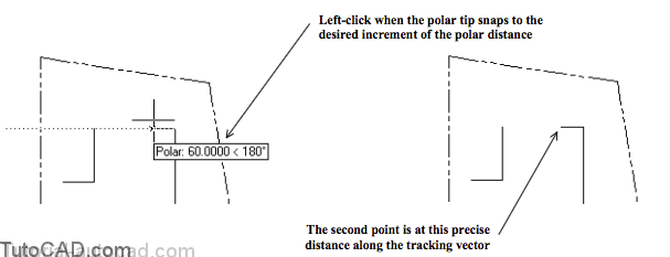
» 14) Move your crosshairs until you see Polar: 72.0000 < 180 as the tooltip & then left-click to use this as the second point of the LINE. The Line command should still be running.
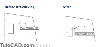
You snapped to a point that was precisely 72 drawing units along the Polar Tracking vector in the 180 degree direction
- so the new LINE is exactly 72 inches long.
- SNAP must be On to use Polar snap points.
» 15) Move your crosshairs so your Tooltip has a polar angle of 210 degrees (distance is not important) and then enter 48 at the keyboard as the distance. Line should still be running.
You used the direct distance entry method to specify a point even though SNAP was On.
- the Polar Tracking vector was used for the direction but the distance you entered at the keyboard was used instead.
» 16) Left-click on SNAP to toggle this setting Off.
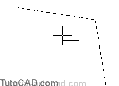
» 17) Move your crosshairs to the Endpoint shown below and left-click to accept the point. Then press <enter> to complete Line.
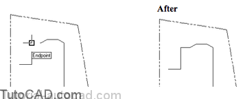
You created these precise LINEs with very little keyboard activity.
- you could continue to add precise geometry (without changing drafting settings) with little typing or menu picks required.
» 18) Make LEGAL the current Layer.
» 19)Right-click on the POLAR status bar button and selectSettings from the shortcut.
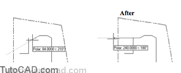
» 20)Select Relative to last segment as the Polar Angle measurement and pick OK.
21) Pick Draw + Line and hold your cursor near P1 until you see an AutoSnap marker and then press <Tab> until the top line is highlighted and an Endpoint marker appears. Then left-click to select this point.
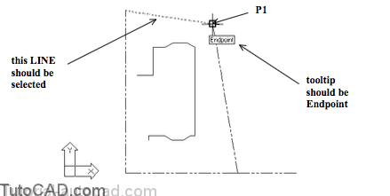
In the next step you will use relative polar tracking and it is important that the upper LINE is selected
- if you did not press <Tab> you could not be sure which of the two LINEs would be used.
- in the next step you would like to draw a new LINE parallel to the upper LINE using Polar Tracking.
22) Move your crosshairs around and observe how all tracking angles are relative to the direction of the selected LINE. Move your crosshairs to the location shown below so the Polar Tracking Tootip has a Relative Polar Angle of 0 and enter 528 as the distance. Press <enter> to complete Line.
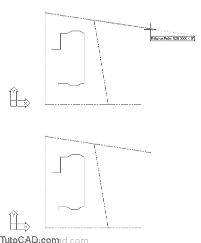
The POLAR tool is far more flexible than the ORTHO tool and you can modify POLAR settings on-the-fly.
» 23) Save the changes to T204_2.dwg for the next exercise.