How to use Quick Leaders
Free AutoCAD course how to use Quick Leaders

You can use leaders to add notes (annotations) that point to specific objects in your drawing.
- this can create an MTEXT object (annotation) & another object that points to the desired area of the drawing (lines & arrows).

You can change settings by right-clicking in the drawing area at the first Qleader prompt & selecting Settings from the shortcut.
- changes made to Settings are saved in your drawing so you can have different settings in different drawings.
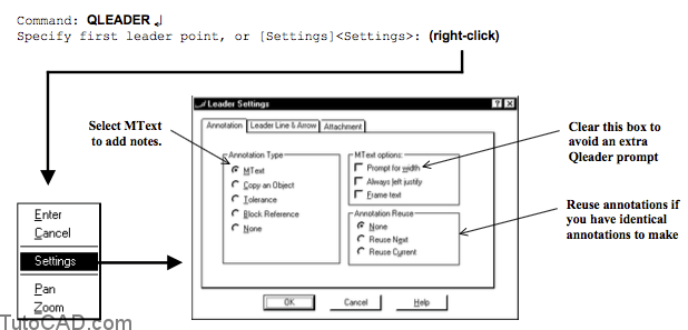
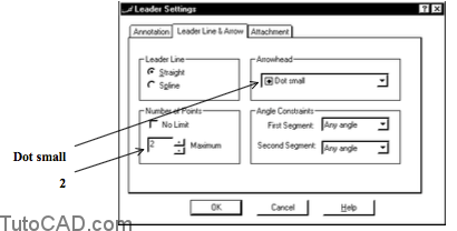
Reduce the amount of clicking required by setting a maximum number of points to be prompted for when you create the leader.
– use 2 points to create only one segment (plus a small tail).

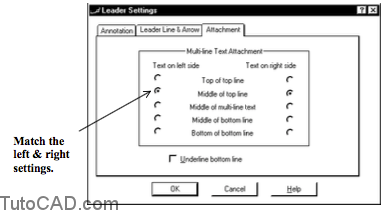
- The Attachment tab for Qleader specifies how to attach the leaders to your annotations.
- – you can have different attachment methods for text on the left compared to when text is on the right.
- – this setting becomes important when you have more than one line in text annotations.

- When you check Underline bottom line on the Attachment tab all of the other settings will be unavailable
- – and the annotation is placed above a horizontal leader line.
Practice : AutoCAD quick leaders tutorial
1- Close the drawing from the previous exercise if it is open.
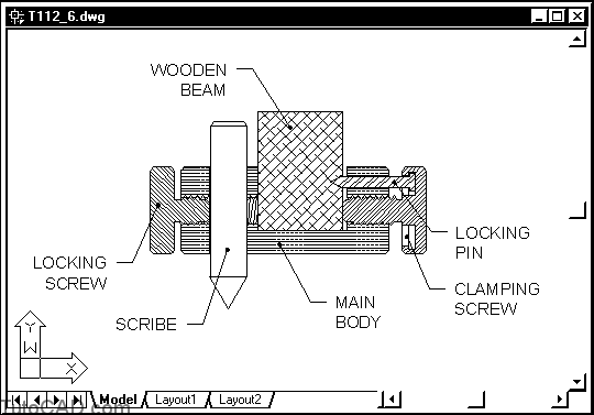
2- Open the T112_6.dwg drawing in your personal folder.
3- Pick Dimension + Leader and right-click in the drawing area to invoke a shortcut. Select Settings. Uncheck the Prompt for width box for MText options then pick the Leader Line & Arrow tab to continue.

4- Select Dot small for the Arrowhead. Enter 2 as the Maximum number of points. Pick the Attachment tab to continue.
So far you have made two adjustments that will save time (“quick” leader) when you create leaders.
– you eliminated the prompt for width (of the MTEXT object) so you do not have to specify a width each time (it will use a zero width)
– and you set the maximum number of points to 2 so that you will only be prompted for 2 points.
5- Select Middle of top line for the Text on left side (to match Text on right side). Then pick OK to continue.
6- Left-click on the OSNAP status bar button to turn this setting Off (if it is On).
7- Follow the command line history below to complete the first leader object shown.
Specify first leader point, or [Settings]<Settings>: (pick by eye near P1)
Specify next point: (pick by eye near P2)
Enter first line of annotation text <Mtext>: LOCKING ↵
Enter next line of annotation text: SCREW ↵
Enter next line of annotation text: ↵
Command:

You can continue to add as many lines for the MTEXT object as you wish and when you are finished adding lines you press <enter>.
– you can use the Multiline Text Editor to create the MTEXT object if you press <enter> at the first MTEXT prompt instead.
Now on your own…
8- Now that you have set your preferences for Quick Leaders in this drawing, complete the other leaders as shown below.
More practice ?
9- Erase all leaders & make them look like the ones shown.

10- Save the changes to this drawing & Close the file.