Temporary Tracking Points in AutoCAD: An Overview
AutoCAD, a software application developed by Autodesk, is an essential tool in various professional fields like architecture, engineering, and design. One of its powerful yet often underutilized features is the Temporary Tracking Points (TTP) function. This function is a key player in improving drawing efficiency and accuracy by allowing users to create reference points in the drawing space, which are temporary and do not affect the final drawing.
Understanding how to use Temporary Tracking Points in AutoCAD can significantly streamline your design process. This comprehensive guide will walk you through what TTP is, its benefits, how to use it, and best practices to maximize its utility.
What is Temporary Tracking Point?
In AutoCAD, a Temporary Tracking Point is a specified point on an object, acting as a reference point that helps you draw precisely. It’s a virtual marker that doesn’t contribute to the final drawing but serves as a guide for accurate drafting.
Benefits of Using Temporary Tracking Points
- Precision: Helps create precise alignments without the need for construction lines.
- Flexibility: Makes it easy to define points relative to existing points in the drawing.
- Efficiency: Eliminates the need for tedious measurements and calculations.
How to Use Temporary Tracking Points in AutoCAD
- Launch AutoCAD: Start by opening the AutoCAD application on your computer. Open the drawing you wish to work on or start a new one.
- Choose a Command: Select the command you wish to use. The TTP function works with various commands like
LINE,CIRCLE,ARC, etc. - Activate TTP: After choosing a command, move your cursor over the object or point where you want to set the Temporary Tracking Point. A small box will appear indicating AutoCAD has recognized it.For example, if you’re working with a line, you might place your TTP at the midpoint, endpoint, or any point along the line.
- Set TTP: Press
Shiftand right-click your mouse to open the context menu. Select theTemporary Tracking Pointoption. - Specify a Point: After setting the TTP, you’ll need to specify a point relative to the TTP. You can do this by moving your cursor and observing the temporary tracking vector that extends from the TTP. Type in the distance and angle, then press
Enter. - Draw with Precision: You can now draw relative to the Temporary Tracking Point with precise accuracy.
The process might vary slightly depending on the command you’re using and what you’re trying to achieve. However, the above steps give a general guide on how to use TTP.
Example:
For example, you could create a CIRCLE (hole) that is 0.5 units from the corner by using the From tool as shown below.
Command: CIRCLE↵
Specify center point for circle or [3P/2P/Ttr (tan tan radius)]: FROM ↵
Base point: (invoke ENDPOINT osnap near P1)
<Offset>: @0.5,0.5↵
Specify radius of circle or [Diameter]: D ↵
Specify diameter of circle: 0.5 ↵
Command:
![]()
- You could perform the same task using Temporary Tracking Points in the following way.
- Command: CIRCLE↵
Specify center point for circle or [3P/2P/Ttr (tan tan radius)]: TT ↵- acquire the Endpoint shown below as an alignment point.
![]()
- invoke a 0 degree tooltip angle then type 0.5 and press <enter> to use direct distance entry for the temporary tracking point.
![]()
- invoke a 90 degree tooltip angle then type 0.5 and press <enter> to use direct distance entry for the CIRCLE center point.
![]()
Here’s a basic table summarizing these steps:
| Step | Action |
|---|---|
| 1 | Launch AutoCAD |
| 2 | Choose a Command |
| 3 | Activate TTP |
| 4 | Set TTP |
| 5 | Specify a Point |
| 6 | Draw with Precision |
Best Practices for Using Temporary Tracking Points
While the TTP function in AutoCAD is straightforward to use, the following practices will help you get the most out of it:
- Use with Object Snap: By combining the Temporary Tracking Point feature with the Object Snap (OSNAP) tool, you can automatically snap to precise locations on objects.
- Shortcut Use: Use the
TTshortcut for faster access to the TTP function. - Regular Practice: As with any skill, the more you use the TTP feature, the better you’ll get. So, practice incorporating TTPs into your regular drafting routine.
Advanced Techniques: Temporary Tracking Points
For users looking to elevate their drafting skills further, AutoCAD allows multiple Temporary Tracking Points to be set at a time, creating a network of reference points for complex drawings.
Additionally, by combining TTPs with other advanced features like Polar Tracking and Object Snap Tracking, you can enhance your drafting accuracy and efficiency further.
Practice: using temporary tracking points tutorial in AutoCAD
- Close the drawing from the previous exercise if it is open.
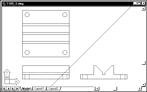
- Open the T109_3.dwg (download the zip file here: T109_3.dwg) drawing in your personal folder.
You will use temporary tracking points in this exercise to position the hole CIRLCEs in each corner as shown here.
![]()
- Pick Draw + Circle + Center,Diameter.
- Pick the Temporary Tracking Point button in the Object Snap toolbar or on the flyout of the Standard toolbar. (you can also type TT if you prefer not to use a button).
- Move your crosshairs over the Endpoint marker shown below to acquire it as an alignment point.
![]()
You are using Object Snap Tracking to specify the Temporary Tracking Point.
– and you will use direct distance entry as well.
- Move your crosshairs to the right so the tooltip angle is 0 and type 0.5 then press <enter> to use this as a temporary tracking point.
 Move your crosshairs upward to invoke a tracking angle of 90 then type 0.5 and press <enter> to use this point as the CIRCLE center. Enter 0.5 as the CIRCLE diameter to complete the Circle command.
![]()
You acquired a tracking alignment point that was not on an object snap point by using the TT (Temporary Tracking Point) utility
– you could continue using TT to supply any number of intermediate tracking alignment points in the same command.
- Use a similar technique to create the remaining CIRCLEs in the other corners.
![]()
More practice?
- Drop down the Layer list in the Object Properties toolbar and left-click on the light bulb icon for the Construction Lines layer to turn this layer On. Then roll up the list. A construction XLINE on this layer has already been created to help generate the missing LINEs in the top view.
![]()
- Pick Draw + Line and enter TT to invoke the temporary tracking point utility. Then acquire a tracking alignment point at the Endpoint marker shown below.
![]()
- Move your crosshairs upward to invoke the Endpoint: Intersection tooltip and left-click to use this point as a temporary tracking point.
![]()
- Move your crosshairs to the left to invoke the Track Point: Intersection tooltip and left click to use this point as the start of the LINE.
- Now you are ready to create a LINE object that will represent this feature edge in the top view.
- You could have simply used Line to create two temporary LINE objects between the three points that you have picked so far - but you would have to Erase the temporary LINE obejcts after you create the desired LINE object. - the tracking approach saves time because you create only the desired objects (there is nothing to Erase at the end).
- Invoke the Polar: Intersection tooltip shown and left-click to use this as the second point of the LINE. Then press <enter> to terminate Line.
![]()
- Use a similar technique to complete the top view by adding the remaining 5 LINEs.
- Save your changes to the drawing and Close the file.
Frequently Asked Questions
1. Are Temporary Tracking Points Visible in the Final Print?
No, Temporary Tracking Points (TTPs) are not visible in the final print of your AutoCAD drawing. TTPs serve as virtual markers in the drawing space and are not actual entities within the drawing. Their purpose is to provide reference or guidance while drafting, and they are temporary in nature.
As such, TTPs do not affect the final printout or output of your drawing. They exist only during the drafting process. Once the command is executed, the tracking point disappears. This means that even if you save your work and reopen it, you won’t find the TTPs you previously placed.
That’s the beauty of TTPs: they provide critical guidance and precision during the drafting phase without leaving a trace in the final output. This function maintains the cleanliness and professionalism of your final drawing while still providing essential drafting support.
2. Can I Use Temporary Tracking Points with All AutoCAD Commands?
While TTPs are versatile and work with a wide array of commands in AutoCAD, there may be a few commands that don’t support them. TTPs are most commonly used with commands that involve creating new shapes or modifying existing ones, such as LINE, CIRCLE, ARC, MOVE, and ROTATE, to name a few.
However, commands that don’t require specific points or directions, like some system variable changes or settings commands, won’t have any use for TTPs. In short, TTPs are functional where the specification of precise points or directions is necessary.
As a best practice, always refer to the official AutoCAD documentation or community forums if you’re unsure whether a particular command supports the use of TTPs. It’s a dynamic software with frequent updates and changes, so staying informed is key to getting the most out of its features.
3. How Many Temporary Tracking Points Can I Use at Once?
AutoCAD allows you to use multiple Temporary Tracking Points at a time, which can be extremely useful in complex drawings that require various reference points. The number of TTPs you can use simultaneously is not explicitly limited, allowing you a wide scope for precision and flexibility.
When using multiple TTPs, remember that each TTP serves as an individual reference point. By setting multiple TTPs, you’re essentially creating a network of reference points that can help you accurately construct more complex shapes and designs.
However, it’s important to note that using too many TTPs can make the drafting process more complicated. It’s recommended to use only as many TTPs as necessary for a given task to keep the process manageable and efficient.
4. Can I Save Temporary Tracking Points?
Temporary Tracking Points in AutoCAD are, by definition, temporary. They serve as guide points while you are working on a specific command. Once that command is completed, the TTP disappears. As such, TTPs cannot be saved for later use.
TTPs are intended to help with the current drawing task. Once you finish that task, the point has served its purpose and is no longer needed. Therefore, there is no function in AutoCAD to save these points.
However, if you frequently use specific reference points in your drawing tasks, you may consider creating a block or using layers to mark these points for easy future access. Always remember that the TTP’s purpose is to streamline your drafting process, not complicate it.
5. What’s the Difference Between Temporary Tracking Points and Object Snaps?
Temporary Tracking Points and Object Snaps (OSNAPs) are both tools in AutoCAD that help increase precision while drafting. However, they serve slightly different functions.
OSNAPs allow you to snap to a specific part of an existing object, such as the endpoint of a line or the center of a circle. This feature is incredibly useful for ensuring accuracy in your drawings by providing precision when selecting points on existing objects.
On the other hand, TTPs are not attached to specific points on existing objects. Instead, they serve as freely placed guide points in the drawing space. These points don’t interact directly with your objects, but they provide reference points that can be used in conjunction with various commands.
Although different in function, these two tools can be used together for maximum precision and efficiency. You might use an OSNAP to set a TTP on a specific point on an object, for instance.
6. Can I Use Temporary Tracking Points in 3D Drawings?
Yes, you can use Temporary Tracking Points in 3D drawings. The ability to use TTPs in a 3D space is one of the aspects that make AutoCAD such a powerful tool for 3D modelling.
In a 3D drawing, TTPs work much the same way as in 2D. You can set the TTP on a specific point on your 3D object, and AutoCAD will provide a tracking vector that you can use to define new points relative to the TTP.
This feature is incredibly useful for creating precise and complex 3D models. Whether you’re designing architectural structures or intricate mechanical parts, the use of TTPs can significantly enhance your precision and efficiency.
7. Can I Adjust the Visibility of Temporary Tracking Points?
Temporary Tracking Points do not have a visible marker or symbol in the AutoCAD workspace. Instead, their presence is indicated by a tracking vector—a dashed line that extends from the TTP when you move your cursor.
While you can’t change the visibility of the TTP itself, you can customize the appearance of the tracking vector in the AutoCAD settings. The settings allow you to change the color, linetype, and lineweight of the tracking vector, which can improve visibility depending on your drawing’s complexity and color scheme.
Remember that these settings affect all tracking vectors in your drawing, not just those associated with TTPs. Therefore, it’s essential to consider how these changes will impact your overall drawing experience.
In summary,
Understanding how to use Temporary Tracking Points in AutoCAD allows you to draw more accurately and efficiently. It is a skill worth mastering to enhance your CAD drafting capabilities. Keep practicing, and soon, this powerful tool will become an integral part of your drafting process.