Basic Tools Review
The default mode for selecting objects (e.g. in edit commands) is to use your pickbox to select objects one at a time.
- use the pickbox when you must select only a few objects.
- if you must select more than a few objects you should be using amore effective selection tool than this.
You can change the pickbox size on the Selection tab of the Options dialogue box
|
||
|
||
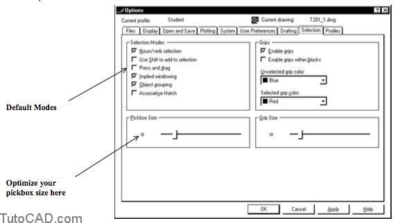
You can also change Selection Modes in this box.
- the initial default settings are shown above and the resulting behavior is used in this document.
- use Help for PICKFIRST, PICKADD, PICKDRAG, & PICKSTYLE system variables to learn more about these different modes.
Window is used to select only those objects that reside entirely within a rectangular window specified by two corner points.
- type W at “Select objects:” prompt to explicitly use aWindowselection tool.
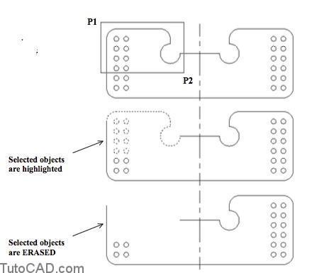
Command: ERASE ↵
Select objects: W ↵
Specify first corner: (pick near P1)
Specify opposite corner: (pick near P2)
13 found
Select objects: ↵
Command:
You can use an implied Window selection tool by picking in empty space (with your pickbox) at the “Select objects” prompt.
- AutoCAD assumes you want an implied Window (or Crossing) if your pickbox is not above an object when you left-click.
- when you are asked to “Specify opposite corner” you should pick this point to the right of the first point for an implied Window.
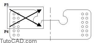
Command: ERASE ↵
Select objects: (pick empty space near P3 or P4)
Specify opposite corner: (pick point to the right)
13 found
Select objects: ↵
Command:
Crossing is used to select objects that either reside entirely within a rectangular box or are crossed by that box.
- typeCat “Select objects:” prompt to explicitly use aCrossingselection tool.
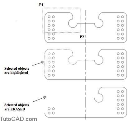
Command: ERASE ↵
Select objects: C ↵
Specify first corner: (pick near P1)
Specify opposite corner: (pick near P2)
13 found
Select objects: ↵
Command:
You can use an implied Crossing selection tool by picking in empty space (with your pickbox) at the “Select objects” prompt.
- AutoCAD assumes you want an implied Crossing (or Window) if your pickbox is not above an object when you left-click.
- when you are asked to “Specify opposite corner” you should pick this point to the left of the first point for an implied Crossing.
Command: ERASE ↵
Select objects: (pick empty space near P3 or P4)
Specify opposite corner: (pick point to the left)
13 found
Select objects: ↵
Command:
WPolygon
WPolygon is like Window except the boundary can have more than four sides.
- type WP at the “Select objects” prompt to invoke WPolygon then pick points along a polygon.
- press <enter> to close the last side of the boundary and selected objects are those that reside entirely inside the boundary.
Command: ERASE ↵ Select objects: WP ↵
First polygon point: (pick P1)
Specify endpoint of line or [Undo]: (pick P2)
…
(keep picking points around the desired boundary)
…
Specify endpoint of line or [Undo]: (pick P3)
Specify endpoint of line or [Undo]: ↵
24 found
Select objects: ↵
Command:
CPolygon
CPolygon is like Crossing except the boundary can have more than four sides.
- type CP at the “Select objects” prompt to invoke CPolygon then pick points along a polygon.
- press <enter> to close the last side & selected objects are either entirely inside the boundary or are crossed by this boundary.
Command: ERASE ↵
Select objects: CP ↵
First polygon point: (pick P4)
Specify endpoint of line or [Undo]: (pick P5)
…
(keep picking points around the desired boundary)
…
Specify endpoint of line or [Undo]: (pick P6)
Specify endpoint of line or [Undo]: ↵
27 found
Select objects: ↵
Command:
Fence lets you draw a fence with straight segments to select all objects crossed by the fence (NOT enclosed by the fence).
- type F at the “Select objects” prompts to invoke Fence then pick as many points as you wish to define the desired fence.
- press <enter> when you are ready to apply the fence.
Command: ERASE ↵
Select objects: F ↵
First fence point: (pick P1)
Specify endpoint of line or [Undo]: (pick P2)
Specify endpoint of line or [Undo]: (pick P3)
Specify endpoint of line or [Undo]: ↵
4 found
Select objects: ↵
Command:
You can use the Fence tool to select more than one object to Trim or Extend in one step.
- simply enter F when AutoCAD prompts you to select objects toTrim or Extend.
- it is important where you select objects in these commands and you can control this by where you place your fence.
All
Use All to select all objects on thawed layers in the current space.
- Type ALL (the entire word) at the “Select objects” prompt to invoke the All tool.
- objects on thawed layers are selected even if they are not displayed on-screen (or are on layers that are turned off).
PREVIOUS
Use Previous to select the same objects that you have already selected in the previous edit command.
- type P at the “Select objects” prompt to invoke Previous.
- AutoCAD will tell you “No previous selection set” if the Previous tool does not select any objects.
LAST
Use Last to select the youngest object (the object created most recently) that is currently displayed on-screen.
- type L at the “Select objects” prompt to invoke Last.
- if there are no objects currently displayed on-screen the Last tool will not select any objects.
- the Last tool will not select the last object that you created unless this object is visible on your screen.
ADD / REMOVE
When you see the “Select objects” prompt you are in Add mode which means selected objects are added to the selection set
you can continue to add objects to your selection set using any number of the selection tools described in the previous pages.
- pressing <enter> at the “Select objects” prompt signals AutoCAD that you have finished defining your selection set.
- you can continue to add objects to your selection set using any number of the selection tools described in the previous pages.
If you select objects by mistake you can press & hold <Shift> while you select them again to remove them from the selection set.
- you can also type R at the “Select objects” prompt to switch to Remove mode and AutoCAD prompts you to “Remove objects”.
- you can use the same selection tools in Remove mode to remove selected objects from the current selection set.
You can type A at the “Remove objects” prompt to return to the Add mode and the “Select objects” prompt.
- or you can press <enter> to complete the selection set.
PRACTICE USING SELECTION TOOLS
1) Launch AutoCAD (if required). Pick File + Open and select the T201_1.dwg drawing file in your personal folder. Close all other drawings (if other drawings are open).
2) Pick Tools + Run Script. Select the T201.scr script file in your personal folder and pick the Open button there to run this script. This sets several system variables to match the behavior illustrated in this manual.
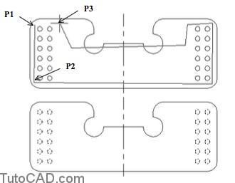
3) Pick Modify + Erase and when prompted to select objects hold your pickbox in empty space near P1 and left-click to signal AutoCAD that you want to use an implied Window.
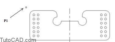
4) Move your crosshairs near P2 to form a box shown below and left-click to use this implied Window. Do NOT press<enter> yet because you will change this selection set in the next step.
AutoCAD reminds you this is an implied Window by displaying the box using a continuous line (Crossing uses a highlighted box).
5) Press & hold your <Shift> key while you select the ARC near P1 again using your pickbox. This removes the ARC from the current selection set (it is no longer highlighted).
6) Press <enter> at the “Select objects” prompt to signalAutoCAD that you are finished selecting objects and AutoCAD will Erase the current selection set.
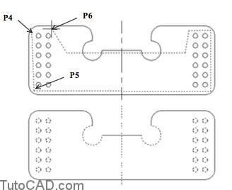
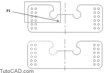
7) Right-click in the drawing area to invoke a shortcut and select Repeat Erase. Type WP at the “Select objects” prompt to invoke the WPolygon tool. Pick by eye near P2,P3, P4, P5, P6 then P7. Press <enter> to close the polygon from P7 to P2 & press <enter> to Erase the CIRCLEs.
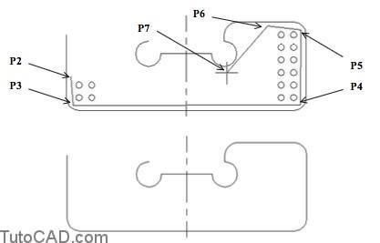
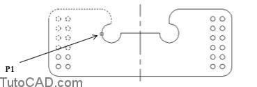
The center line was NOT Erased because it did not reside entirely inside the WPolygon boundary.
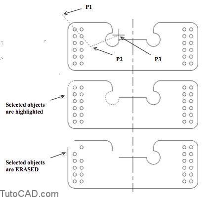
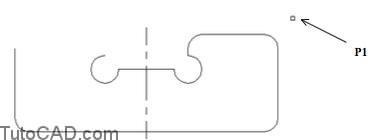
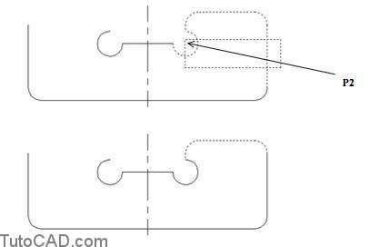
8) Pick Modify + Mirror. When prompted to select objects hold your pickbox in empty space near P1 and left-click to signalAutoCAD that you want to use an implied Crossing tool.
9) Move your crosshairs to the left near P2 to form the box shown then left-click to use this implied Crossing box. Do NOT press <enter> yet because you will continue to change this selection set in the next steps.
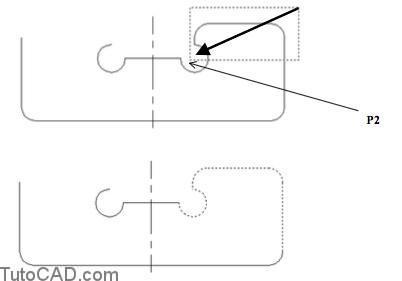
You picked the second point of this box to the left of the first point which signals AutoCAD to use an implied Crossing tool.
- picking the second point to the right implies a Window tool.
- the box is highlighted to remind you that this is a Crossing box (a Window box is displayed using continuous lines).
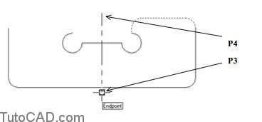
10) Press & hold your <Shift> key while you move your pickbox to an empty space near P1 and left-click to use another implied Crossing tool.
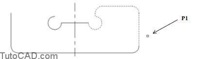
11) Move your crosshairs to the left near P2 to form the box shown and left-click to use this implied Crossing box to remove the ARC and LINE from the current selection set.
12) Press <enter> to complete your selection set. Left-click on the OSNAP status bar button (if it is not already On) and invoke the Endpoint osnap near P3 as the first point of the mirror line. Use an Endpoint osnap at the other end of the center line near P4 as the second point of the mirror line and press <enter> to keep the original objects.
You used a variety of selection tools to manipulate this drawing.
- you could have easily achieved the same results in this simple drawing using only your pickbox
- but when you work on more complex drawings the pickbox approach to selecting objects will be tedious & inefficient.
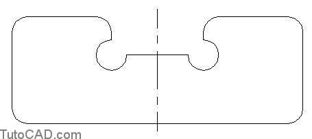
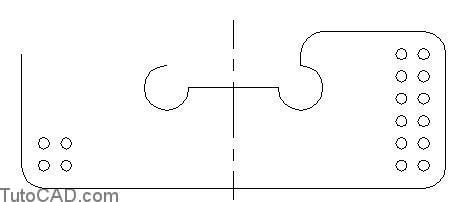
13) Left-click on the Layout2 tab to see another part that is still under construction.
![]()
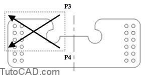
14) Pick Modify + Trim. Select the CIRCLE near P1 using your pickbox and press <enter> to continue.
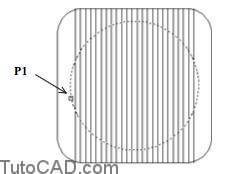
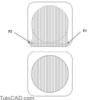
15) Left-click on the OSNAP status bar button to turn it Off (if it is On). Type F to invoke the Fence tool when prompted to select objects to trim. Pick near P2 then P3 and press <enter> to apply this Fence (but do not terminate Trim).
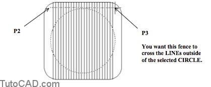
16) Type F again at the prompt to select objects to trim and pick near P1 then P2. Press <enter> to apply this Fence and press <enter> again to terminate Trim.
More practice?
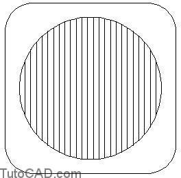
17) Continue to Trim these LINEs and create the openings in this plate as shown below.
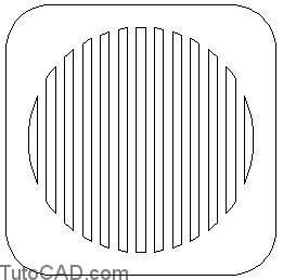
Press <enter> when prompted to select the cutting edges (i.e. do not pick any cutting edges)
- AutoCAD will then assume that all objects are cutting edges soyou can go to work picking objects to Trim (one at a time).
18) Save the changes to your drawing & Close the file.