Drawing Setup Overview
Here is how to setup a new drawing in AutoCAD
Drawing setup is very important when you create new drawings using AutoCAD.
- if you organize drawing setup properly you will save time later on and your drawings will have a more consistent appearance.
This section is an overview of drawing setup concepts and you should not be concerned if you are (initially) confused.
- the many aspects involved in setting up a drawing to suit your application can be overwhelming when you are new to AutoCAD.
- drawing setup will make more sense to you later in the course as you learn more about these concepts.
- System Variables
Drawing setup is controlled primarily by system variables and these variables can be saved in drawings or saved in your system registry.
- one way to change many AutoCAD system variables is to use the Options command.
- there are numerous tabs in the Options dialogue box to control settings for various functions.
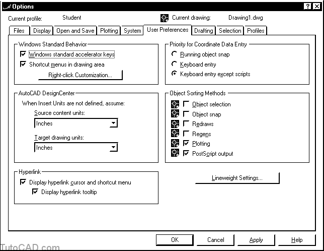
Preferences saved in drawing files have this icon next to the description. Other preferences are saved in your system registry.
If you share your computer system with other people you should consider setting up your own Profile to save your settings.
- profiles are created and managed using the Profiles tab of the Options command.
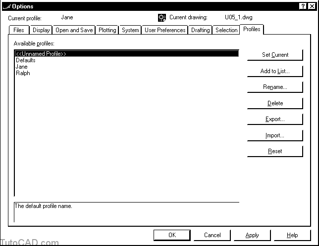
Each user can have his or her own profile where their preferences for system variables can be stored.
Not all settings can be changed in the Options dialogue box or saved in your personal profiles.
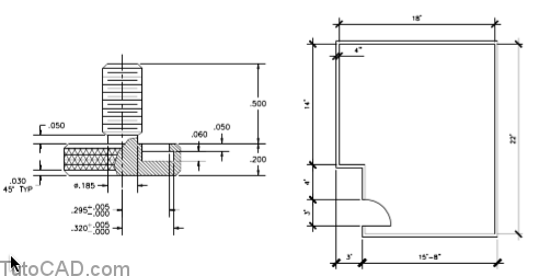
- for example, more than 60 variables (specific to dimensions alone) can be changed using the Dimstyle command.
- dimensions can take on a variety of different styles depending on how you set the dimension variables in your drawings.
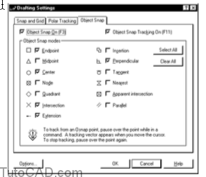
Drafting tools are also controlled by many different system variables and most of these variables are saved in your system registry.
- you can change some of the variables associated with drafting tools using the settings dialogue box.
- other drafting tool variables can be changed on the Drafting tab of Options (you can also pick Options from the Dsettings box).
Drawing setup also involves creating & using appropriate Layers.
- you can manage your drawings more efficiently and have better control when you Plot if you place objects on appropriate layers.
Most drawings contain text and AutoCAD supports a wide range of fonts, including TrueType and Postscript fonts.
- you should set up your drawings with the Style command to automatically use appropriate fonts for text.
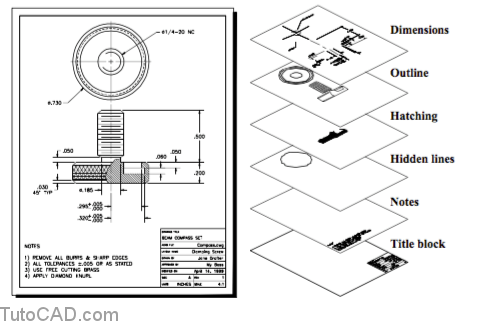
NOTES
1) REMOVE ALL BURRS & SHARP EDGES
2) ALL TOLERANCES ±.005 OR AS STATED
3) USE FREE CUTTING BRASS
4) APPLY DIAMOND KNURL
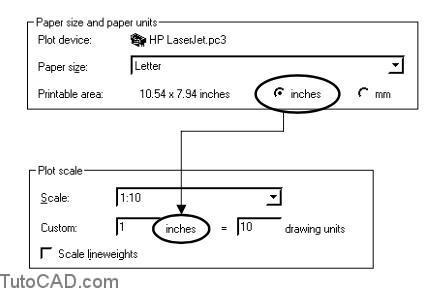
You can use Pagesetup before you Plot your drawings and select either Inches or mm for the paper units (see also page 11).
- if the paper units are the same as your drawing units it is easier to specify a plot scale.
- so AutoCAD works best when the drawing units in your CAD model also represent either inches or millimeters.
You can let drawing units represent any other real world units (other than inches or mm)
- but you will have to adjust the plot scale accordingly.
Many system variables must be adjusted appropriately once you decide what a drawing unit represents in your CAD model.
- these variables control such things as text height, dimension feature size, crosshatching scale, linetype scale etc..
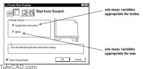
- you will find AutoCAD much easier to work with if you create your models using either inches or mm as the drawing units.
You may also want to adjust the way distances and angles are formatted using the Units command.
- you do NOT change the size of objects in your drawing when you change these Drawing Units settings.
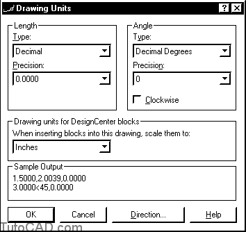
Some Drawing Units settings are only appropriate in drawings created with inches as the drawing units.
- distances are displayed as feet & inches when Architectural or Engineering types are selected for Length.
- however, a drawing unit represents one inch when you display distances using these feet & inches formats.
Drawing scale can affect many parameters like text height, hatch scale, linetype scale, dimension feature sizes & symbol scale.
- there is no single system variable to control drawing scale.
- drawing scale is a factor that you establish for a drawing and you use this factor to adjust many other system variables.
You should always create your model in AutoCAD using the actual dimensions for the objects that you are modeling (i.e. full scale).
- drawing scale in AutoCAD normally involves the scale at which your drawing (or parts of it) will appear when you Plot.
You can begin creating your CAD model before you know what your final drawing scale will be
- but you should establish a target drawing scale early in your drawing project to avoid any extra work later on.
- otherwise, you may have to make adjustments to text, dimensions, crosshatching, symbol sizes, etc..
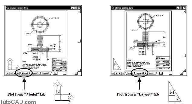
There are two different ways to set up a drawing in AutoCAD and each method uses a different approach to drawing scale.
- you can set up a drawing to Plot from the Model tab which was the method used when AutoCAD was first developed
or you can set up a drawing to Plot from a Layout tab which is becoming the standard approach.
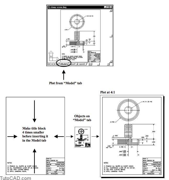
When you set up a drawing to plot from the Model tab you adjust the title block size (larger or smaller) to suit your drawing (plot) scale.
- for example, if you plot at 4:1 (enlarge objects by factor of 4 in the plot) the title block should be 1⁄4 the plotted size in the model.
- so when you Plot from the Model tab the title block would end up being the correct size on paper.
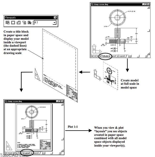
- When you set up a drawing to plot from a Layout tab you draw a title block on the layout at the size it should be when you Plot (true size).
- The model can be created on the Model tab but you can also display and edit the model inside one or more viewports on a Layout tab.
- you control drawing scale by setting an appropriate display magnification for the model in each layout viewport.
- viewports in the layout show your model at the appropriate drawing scale when you Plot layouts at a 1:1 plot scale.
When you work with Layouts you can be in either paper space or model space.
- new objects are created in the current space
- for example, if you draw a LINE when you are in paper space the new LINE object is in paper space.
One way to know which space you are in is to look at the UCS icon (UCS is an abbreviation for User Coordinate System)
- in paper space the UCS icon looks like a drafting triangle.

- in model space the UCS icon looks completely different.

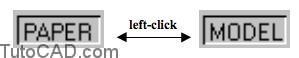
Status bar buttons (at the bottom of your AutoCAD screen) also remind you which space you are in.
- when you see the word PAPER you are in paper space.
![]()
- when you see the word MODEL you are in model space.
![]()
- you can left-click on these status bar buttons to switch spaces (or you can double-click in the desired drawing space instead).
You will learn more about Layouts throughout this course so you should not be too concerned about Layout details right now.
- You must eventually set up your page before you can Plot from either the Model tab or from a Layout tab.
- use the Pagesetup command to set the many different parameters involved in preparing a page for plotting.
- there are two tabs in the Page Setup dialogue box.
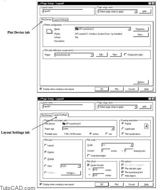
You will work with basic aspects of Page Setup in this document.
- the other parameters will be reviewed again in greater detail later on in the course.
It is a good practice to select a sheet size at the start of a drawing project even if you are not sure what it will be in the final plot
- and you should select a target drawing scale so you can begin to make appropriate adjustments to other system variables.
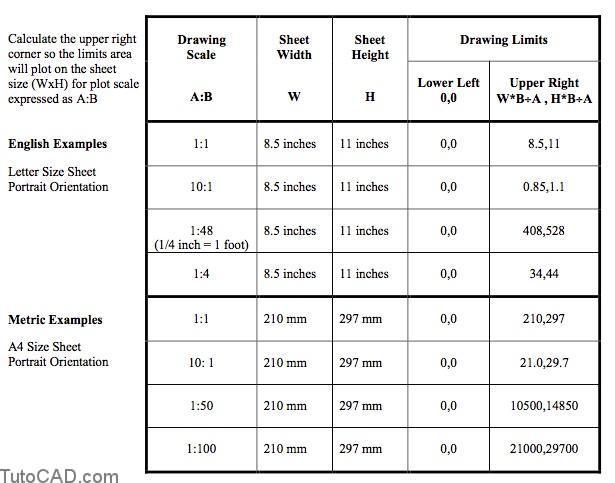
- then change your drawing Limits on the Model tab to account for the sheet size & target drawing scale that you wish to use.
Drawing limits are stored in the drawing as the coordinates for the lower left and upper right corner of your drawing border.
- you can set drawing limits on the Model tab regardless of whether you will Plot from the Model tab or from a Layout tab.
- the following examples show drawing Limits calculations for the Model tab based on sheet size (WxH) & drawing scale (A:B)
If your Limits are larger than your Extents then Zoom All displays the drawing Limits to fit in the available space on-screen.
- you can also select Limits as the area of your drawing to Plot.