Editing MLINEs
You can use Copy, Move, Mirror, Rotate, Scale & Stretch on MLINEs but some edit commands are not supported for MLINEs
- for example, you cannot use Break, Chamfer, Fillet, Trim &Extend on MLINE objects.
- to perform these types of operations on MLINEs you must use the Mledit (multiline edit) command.
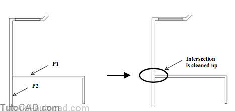
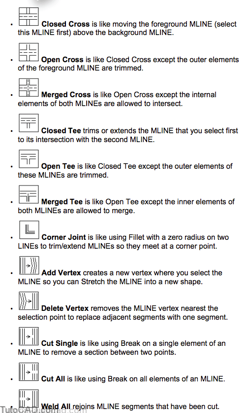
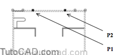
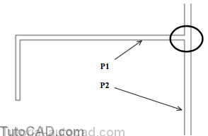
For example, to clean up a Tee intersection where two MLINEs meet you could use the Open Tee option for Mline
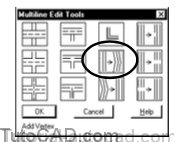
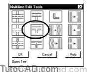
- select the Open Tee icon in the Multiline Edit Tools dialogue box and pick OK.
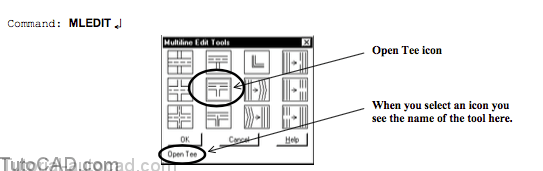
- then select the two MLINE objects to edit with this tool and press <enter> to complete the Mledit command.
Select first mline: (pick MLINE near P1)
Select second mline: (pick MLINE near P2)
Select first mline or [Undo]: ↵
Command:
MLINEs & Grips
You can also use grip editing techniques to change the shape of MLINE objects by moving their vertices to new locations.
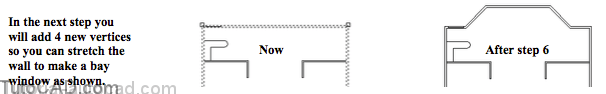
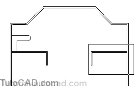
- for example, you could use Mledit to add 4 new vertices in the wall shown below.
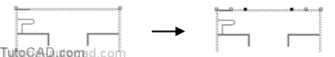
- then you could Stretch two of these vertices using grips to form a bay window along this wall.
As a last resort you may want to use Explode on MLINEs to convert them to LINE objects.
- then you can use other edit commands to modify the resulting LINE objects.
- however, you cannot change these LINEs back into MLINEs.
PRACTICE EDITING MLINES
- Continue with the drawing from the previous exercise(or Open the T208_8.dwg drawing in your personal folder).2)Select the MLINE for the outside walls to display the grips. Then press <esc> twice to clear them.
3) Pick Modify + Multiline. Pick the Add Vertex icon then pick OK to continue.
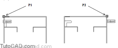
4) Follow the command history below & use the FROM tool and explicit Endpoint osnaps to select the MLINE at precise locations.(vertices are added where you select the MLINE).
Command: MLEDIT ↵
Select mline: FROM ↵
Base point: ENDP ↵
of (left-click for Endpoint osnap near P1) <Offset>: @6′,0↵
Select mline or [Undo]: @6′,0 ↵
Select mline or [Undo]: FROM ↵
Base point: ENDP ↵
of (left-click for Endpoint osnap near P2) <Offset>: @–6′,0↵
Select mline or [Undo]: @ – 6′,0 ↵
Select mline or [Undo]: ↵
Command:
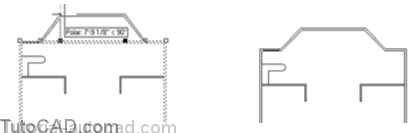
5) Select the outside MLINE again to display the grips. Press & hold the <Shift> key while you left-click on the grips near P1 and P2 to make them both hot.
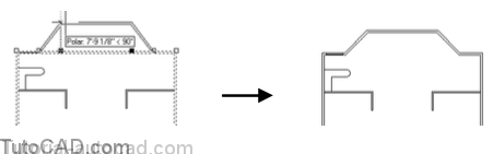
6) Release the <Shift> key and left-click on one of the hot grips again to invoke the Stretch mode. Make sure POLAR is On in the status bar. Move your crosshairs upward to invoke a 90 tooltip angle and enter 6’ (6 feet) as the distance. Press <Esc> twice to clear the grips.
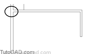
7) Zoom into the window shown below to see a closer view where the two MLINE objects meet.
8) Pick Modify + Multiline. Select the Open Tee icon then pick OK to continue.
9) Pick the MLINE near P1 then pick the MLINE near P2 and press <enter> to complete the Mledit command.
10)Edit the similar joint on the other side of the house using the same technique.
11) Save the changes to your drawing and Close the file.
More Practice
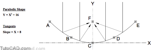
You are asked to model the parabolic section of a satellite dish (this section could be used to fabricate a mandrel for production).
- use the equation to find points A, B, C, D & E for a focal point F of (0,4) if the overall diameter (A to E) of the dish is 16 inches.
- the X component for point B is negative 4 inches and the X component of point D is positive 4 inches.
- create a SPLINE using these 5 calculated points for the tangent directions at each end of 135o & 45o (i.e. @ –1,1 and @1,1 )
- Save the completed file as Dish.dwg in your personal folder.
Open the drawing T208_9.dwg in your personal folder.
- create an MLINE style called SLOT that is similar to the STANDARD style but with Start & End Caps for Arcs.
- use this new MLINE style to create the 0.5 inch diameter slots shown using the POINT objects to snap to with Node osnaps.
- create a REGION that corresponds to the hatched area shown below and find the corresponding area for this REGION.