Extracting Elements from a List with autolisp in AutoCAD
Extracting Elements from a List
There are times when you will want to create a list from other lists. For example, you may want to get a point midway between two other points. To do this you would need the x coordinate of one point and the y coordinate of the other, and then do a bit of math.
Two key functions, (car) and (cdr), are the essential tools in extracting elements from a list. The others, (cadr), (caddr) and (last) can also help you make new lists from existing ones.
Explanation: List extraction functions
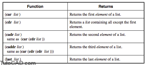
- You can continue to return the next item in a list by adding a “d” to the (caddr) function. Each “d” goes one item deeper into the list. Thus (cadddr) would return the fourth element of a list.
Examples
Command: (setq PT2 (list 1.0 2.0 0.0))
1.0
Command: (car PT2)
1.0
Command: (cdr PT2)
(2.0 0.0)
Command: (cadr PT2)
2.0
Command: (caddr PT2)
0.0
Command: (last PT2)
0.0
Example: Improving on our BOX1.LSP Routine
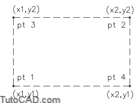
This time we will have the user specify the diagonal corners of a rectangular box. The LISP routine will then calculate the coordinates of the other two corners and draw a box.
(defun c:BOX1 ()
(graphscr)
(setq CE-SAV (getvar “cmdecho”))
(setvar “cmdecho” 0)
(setq PT1 (getpoint “\nEnter first corner of box: ”))
(setq PT2 (getcorner
”))
(setq X1 (car PT1))
(setq X2 (car PT2))
(setq Y1 (cadr PT1))
(setq Y2 (cadr PT2))
(setq PT3 (list X1 Y2))
(setq PT4 (list X2 Y1))
(command “pline” PT1 PT3 PT2 PT4 “close”)
(redraw)
(setvar “cmdecho” CE-SAV)
(princ)
)
- Instead of setting so many variables, you could also create the following two statements in place of the X1, X2, Y1, Y2 and the two PT3 and PT4 settings:
(setq PT3 (list (car PT1) (cadr PT2)))
(setq PT4 (list (car PT2) (cadr PT1)))
- A complete solution to this exercise is on your class disk as BOX1-D.LSP and for the alternate, BOX1-DA.LSP.
PRACTICE
Use Visual LISP to create a file called MIDPT.LSP which will place a circle midway between two points. The midpoint can be derived by adding the respective X, Y, and Z values together, then respectively dividing them by two, then combining them together in a new point. Estimated time for completion: 10 minutes.
Steps to the solution
1. Get a point and store it as PT1.
2. Extract the coordinates as X1, Y1, Z1 from PT1.
3. Get a point and store it as PT2.
4. Extract the coordinates as X2, Y2, Z2 from PT2.
5. Let XMID, YMID, and ZMID be the coordinates of the midpoint.
6. Combine XMID, YMID, and ZMID to form the midpoint, MPT.
7. Place a circle at the midpoint.
Solution
(defun c:MIDPT ()
(setq PT1 (getpoint “\nFirst point: “))
(setq X1 (car PT1))
(setq Y1 (cadr PT1))
(setq Z1 (caddr PT1))
(setq PT2 (getpoint “\nSecond point: “))
(setq X2 (car PT2))
(setq Y2 (cadr PT2))
(setq Z2 (caddr PT2))
(setq XMID (/ (+ X1 X2) 2))
(setq YMID (/ (+ Y1 Y2) 2))
(setq ZMID (/ (+ Z1 Z2) 2))
(setq MPT (list XMID YMID ZMID))
(setq RADIUS (getreal “\nRadius of Circle: “))
(command “Circle” MPT RADIUS)
)
- A complete solution to this exercise is on your class disk as MIDPT-A.LSP