Incorporating Attributes In Block Definitions
You create new block definitions using the Block command.

- begin by typing a Name for the new block definition that will be unique in the active drawing.
- pick Select objects and use selection tools to select the graphical objects & ATTRIBUTE DEFINITIONs.
- pick the Pick point button and use osnaps to select an appropriate base point relative to the selected objects.
- the block definition is stored in the current drawing file but you can use DesignCenter to insert it into other open drawings.
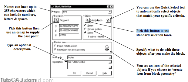
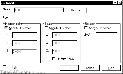
When you Insert a block that has ATTRIBUTE DEFINITIONs defined in it you can specify attribute values in a dialogue box
- but you may have to change the value of the ATTDIA system variable to 1 to use this dialogue box.
- the initial registry value of the ATTDIA system variable is 0 which disables this feature.
ADDING ATTRIBUTE DEFINITIONS TO BLOCK DEFINITIONS
- Continue with the same drawing from the previous exercise (or Open the T207_2.dwg in your personal folder).
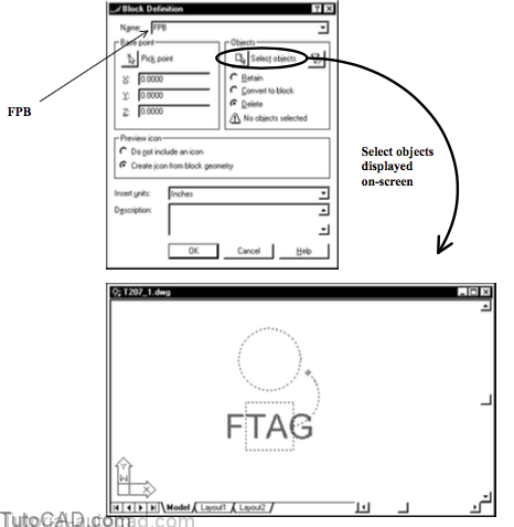
- Pick Draw + Block + Make. Type FPB as the Name. Pick the Select objects button and pick all objects on screen then press <enter> to return to the dialogue box.
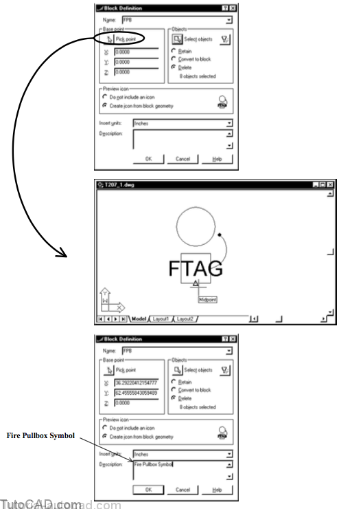
This symbol is normally inserted so that the base is parallel & touching walls in architectural plans.
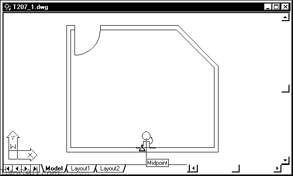
- a logical insertion point for this symbol would therefore be the Midpoint at the bottom of the box.
- in the next step you will use a Midpoint osnap to supply this point as the Base Point of the block definition.3) Pick the Pick point button for the Base point Invoke the Midpoint osnap shown then left-click to use this point. Type the optional description then pick OK.
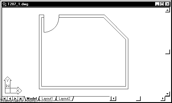
4) Pick View + Zoom + Extents. Then Zoom out more until your screen resembles the illustration below.
5) Type ATTDIA at the command line to verify that this setting is 1 (not the initial default 0).
6) Pick Insert + Block. Select the new FPB block name and make sure Specify on-screen is checked ONLY for Insertion point. Then pick OK to continue.
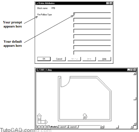
7) Invoke the Midpoint osnap shown below & left-click to use this point as the insertion point.
8) Pick OK to use the default value of F for the attribute.
9) Type I to invoke Insert again. Check Specify On-screen for Rotation and pick OK with FPB still selected as the Name.
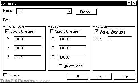
You will be using osnaps to specify the rotation on-screen so that the block insert is aligned with the rotated wall this time.
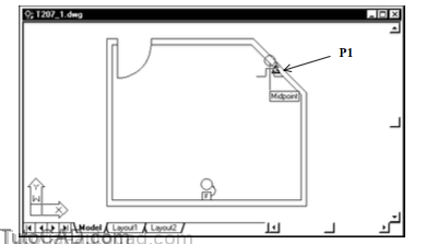
10) Invoke the Midpoint osnap near P1 then left-click to use this as the insertion point.
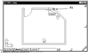
11) Move your crosshairs to invoke the Endpoint osnap near P2 and left-click to use this for the rotation angle.
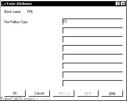
12) This time type F2 as the attribute value and pick OK.
13) Use a similar technique to Insert two more FPB blocks at the Midpoint of the walls as shown such that they are aligned with these walls. Use the attribute values shown.
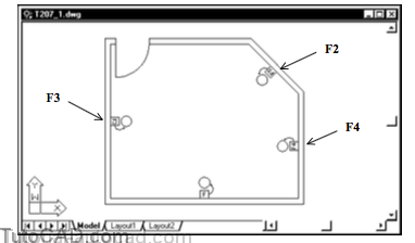
You are able to insert similar symbols as block inserts but each insert can be unique
- you can use a different attribute value in each insert.
14) Save the changes you made to this drawing to prepare for the next exercise.