How to use quick Select & Properties
You can use Qselect (quick select) to automatically find objects that match specific criteria.
- when you use this tool you normally select objects first and thenselect an edit command to use (e.g. Move)
- or you can select the objects using this tool, invoke the desired edit command and then use the Previous selection set.
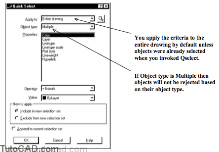
Filter criteria are Applied to the Entire drawing by default
- but the default automatically changes to Current selection if you invoke Qselect when objects are already selected.
If objects are already selected before you invoke Qselect you will probably want to check Append to current selection set
- which will also change Apply to back to Entire drawing again.
Object type is Multiple by default which means all object types are accepted into the selection set
- but you can restrict filter criteria to select objects only if they match the object type selected in the object type drop-down list.
- only object types used in the current drawing are listed in this object type drop-down list.
You can specify How to apply the filter.
- select Include in the new selection set to select objects that match the criteria.
- select Exclude from the new selection set to select objects only if they do NOT match the criteria.
You can select a specific property to include in the filter criteria from the Properties list.
- all searchable properties for the selected object type are included in this list and this may also include custom properties.
- the selected property will also determine what options are available for Operator and Value.
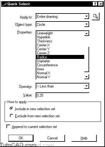
For example, if you restrict the Object type to Circle you could select Radius as one of the Properties
- then you could select < Less than as the Operator and type 0.25 as the Value to look for.
- this criteria would select all CIRCLE objects with a radius that is less than 0.25.
Available Values may also depend on the current drawing.
- for example, if you select Layer as the Property the list of layers defined in the current drawing will be available as a Value.
The Properties command is a powerful tool to change objects using a flexible interface.
- Properties is modeless which means after you invoke it, this tool will remain Open until you explicitly dismiss it.
- it can be docked on the side of your AutoCAD window or you can double-click on the grab bars to make it float as a window.
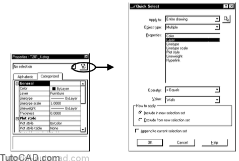
Properties has a Quick Select button that lets you combine these powerful tools.
- you can modify detailed properties of specific objects without having to enter commands or select objects.
- used properly, these tools can save you considerable time.
PRACTICE USING QSELECT & PROPERTIES
» 1) Close the drawing from the previous exercise if it is open.
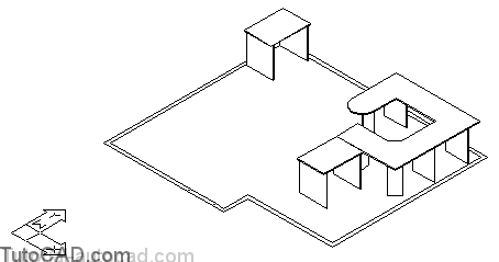
» 2) Open the T201_4.dwg drawing in your personal folder
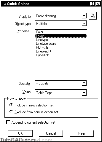
» 3) Pick Tools + Quick Select. Apply to should be Entire drawing. Object type should be Multiple. Select Layer as the Properties and = Equals for the Operator. Select Table Tops as the Value. Include in new selection set should be selected. Pick OK to create the selection set.
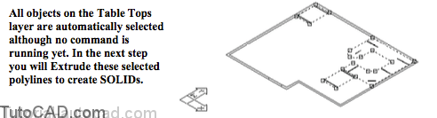
. » 4) Pick Draw + Solids + Extrude. Type P on the command line at the prompt to Select objects and the table top objects will be selected again. Press <enter> to continue. Type 1 as the height and press <enter> to use 0 as the taper angle.
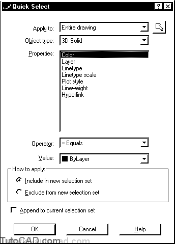
» 5) Pick Tools + Quick Select again. This time select 3D Solid as the Object type. Pick OK without making any other changes to select all of the SOLID objects.
6- Pick Modify + Move. Type 0,0,36 as the displacement and press <enter> as the second point of displacement to move the selected 3D Solids 36 inches above the floor.
Unlike with the Extrude command, these SOLID objects remained selected when you invoked Move
- so you did not have to explicitly use the Previous selection tool to re-select these objects again.
» 7) Pick Tools + Quick Select. Change Properties to Layer and select Table Supports as the Value then pick OK.


8- Pick Draw + Solids + Extrude. Type P on the command line at the prompt to Select objects and the table support objects will be selected again. Press <enter> to continue. Type 36 as the height and press <enter> to use 0 as the taper angle.
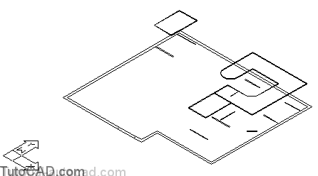
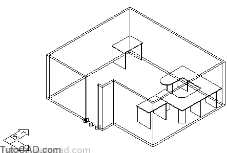
9- Pick View + Hide to see a hidden line view of the completed solid models for these tables.
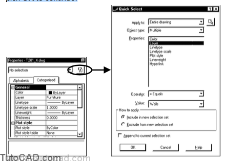
10- Pick Tools + Properties (if Properties is not already open). Then pick the Quick Select button to continue. Change the Properties to Layer and select Walls as the Value. Then pick OK to continue.
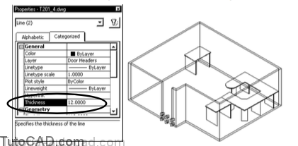
11- Double-click in the box to the right of Thickness in the General category of the Properties box. Type 96 then select the word Thickness to update this change to the THICKNESS property of the selected LINE objects.
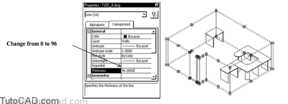
You just made the wall LINE objects 96 inches high by changing the THICKNESS property of all selected LINEs.
- there is a doorway with door header LINEs on a separate layer.
- in the next step you will convert these objects to 3D & change the Z ordinates of these LINEs to move them above the floor.
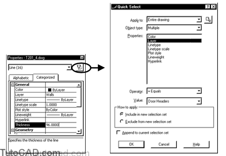
12- Pick the Quick Select button in Properties again. Select Entire drawing for Apply to (objects are still selected so Apply to will be Current selection by default). Select Layer as the Properties and select Door Headers for the Value. Then pick OK to continue.
Now there should be only two LINEs selected in the open doorway.
- in the next step you will change the THICKNESS property of these LINEs to be 12 inches
- and you will change the starting and ending Z ordinates of these LINEs to 84 so that they are 84 inches above the floor.
- this is like using Move to place these LINEs at the desired location above the doorway.
13) Double-click in the box to the right of Thickness in the General category of the Properties box. Type 12 then select the word Thickness to update this change to the THICKNESS property of the selected LINE objects.
14) Collapse the General Category (if required). Double-click in the box to the right of Start Z. Type 84 then select the word Start Z to update the change. Do the same for End Z. Dismiss Properties. Press <Esc> twice to clear the grips.
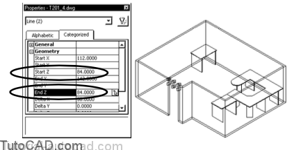
The short wall segment above the open doorway is no longer resting on the floor now that the start & end Z ordinates are both 84 inches.
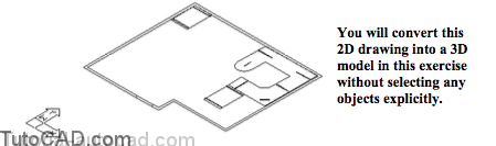
You were able to make all of the changes in this exercise without having to explicitly select any objects.
- Quick Select is an efficient tool to save time.
» 15) Save the changes to this drawing and Close the file.