Raster Image Overview
A raster image file (also called a bitmap or texture file) is a file thatBits per pixelcontains an ordered arrangement of pixels (picture elements).
- each tiny pixel is assigned a specific color so that when you display these pixels (e.g. on your screen) you can see an image.
- raster images are quite different than vector objects (such as ARCs & LINEs) in AutoCAD.
- some of the parameters that characterize raster images are briefly summarized below.
The range of possible values (shades) for each individual pixel is described by the number of bits per pixel.
- you can also refer to the number of colors per pixel instead (the number 2, raised by the power of the number of bits).
- for example, the number of possible colors for each pixel in an 8 bit image is 2*2*2*2*2*2*2*2 = (2)8 = 256 different colors.
- one bit (2 color) images (also referred to as monochrome or bitonal images) have special properties in AutoCAD.
One way to measure image size is by the number of pixels in each row (width) by the number of pixels in each column (height)
- for example, if you capture a typical computer screen the image size could be 1024 pixels wide by 768 pixels high.
Another way to measure image size is by the file size (i.e the number of bytes on disk).
- file size increases when you increase the total number of pixels (width x height) or the number of bits per pixel.
- some raster file types can be saved in a compressed format to minimize file size with only a minor impact on image quality.
Raster images might also be saved with resolution information that is normally expressed as the number of pixels (or dots) per inch.
- this data (if saved in an image), combined with an insertion scale, determines the final image dimensions in AutoCAD drawings.
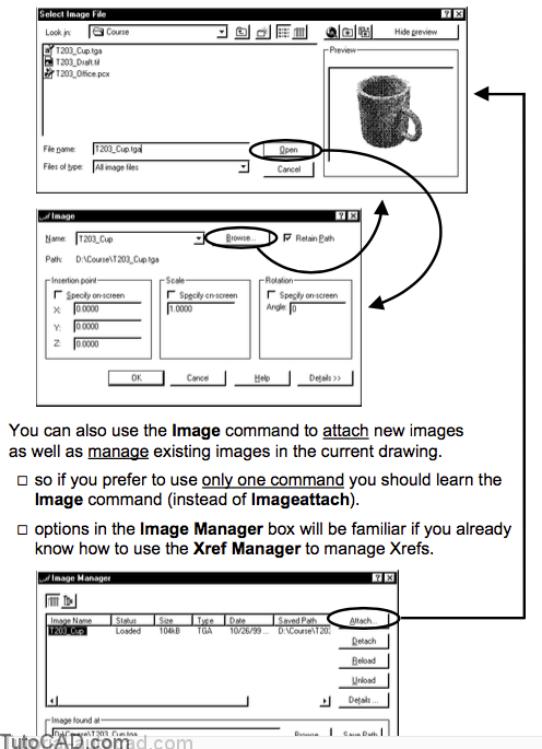
You can use the Imageattach command to explicitly attach images to the current drawing.
- the Image dialogue box will be familiar to you if you already know how to use the Insert command.
Images make it easier for others to understand your designs compared to using only vector drawings.
- for example, you could scan a photograph of a completed part to include in a layout (if your plotter can plot raster images).
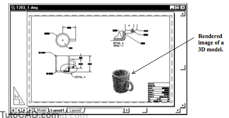
- you could even use AutoCAD to create a rendered image file of a 3D model and attach this to the 2D layout for that model.
You can also combine raster images of 2D drawings with vector 2D drawings and avoid having to re-create old drawings in AutoCAD.
- for example, a co-worker could fax an office plan sketch to your desktop & you could combine it with vector blocks for furniture.

Images are like Xrefs because the images are stored in external image files (not the drawing file).
- if attached image files are not accessible when you Open a drawing you will not see the image in the drawing.
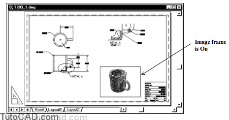
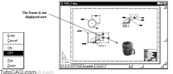
The frame around images is displayed by default but you can use the Imageframe command to toggle all frames on or off.
- you must select image frames to select an Image object.
- it is practical to leave image frames on until you no longer need to select them (e.g. to Move or Scale them).
You must type the entire word, ON or OFF, at the prompt to change settings (or right-click in the drawing for a shortcut).
Command: IMAGEFRAME↵
Enter image frame setting [ON/OFF] <ON>: OFF ↵
Command:
Images are placed on the current layer when you attach them and the entire image is hidden if you turn this layer Off or Freeze it.
- you can change the layer of an image object like any other object (image frames must be visible to select the image object).
If Color is Bylayer (the normal setting) the Image frame will inherit the color of the Image layer.
- if the Image is a one bit (bitonal) image (e.g. black & white) the foreground color of the image will also inherit this color.
if the Image is not one bit (e.g. 256 gray scale) the image layer color will not affect the image colors inside the image frame.
PRACTICE ATTACHING AN IMAGE TO A DRAWING
1) Launch AutoCAD (if required). Open the T203_1.dwg drawing file in your personal folder. Close all other drawings (if other drawings are open).
2) Pick Tools + Run Script. Select the T203.scr script file in your personal folder and pick the Open button there to run this script. This sets several system variables to match the behavior illustrated in this manual.
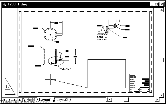
This is a simple 2D drawing of a coffee cup.
- the model is displayed in paper space but viewport borders do not appear because they are on a layer that is turned off.
- in this exercise you will attach a rendered image file of this cup and scale it by eye in Layout1.
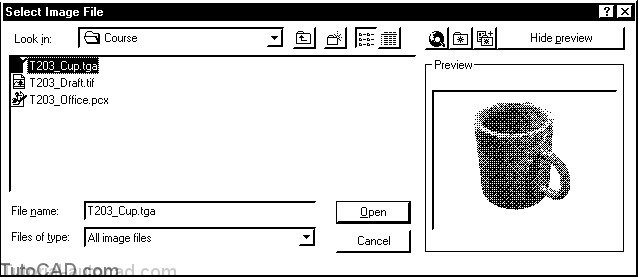
3) Pick Insert + Raster Image. Select T203_Cup.tga in your personal folder and pick Open to continue.
4)Check the Specify on-screen boxes for Insertion point and for Scale but uncheck the Specify on-screen box for Rotation. Then pick OK to continue.
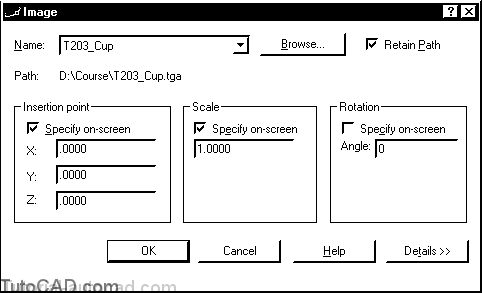
5) Pick near P1 and move your crosshairs near P2 so the dragged rectangle appears as shown below. Then left-click to insert the image at this scale.
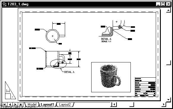
6) Pick Modify + Object + Image + Frame. Then right-click in the drawing area to invoke a shortcut and select OFF.
7) Pick Insert + Image Manager. Select the T203_Cup image and pick the Unload button. Then pick OK.
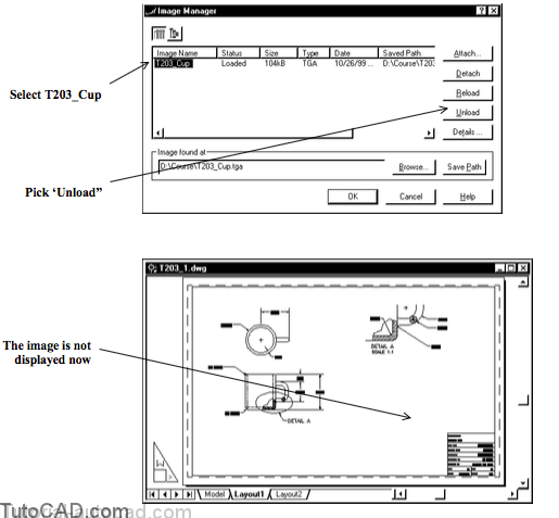
8) Pick Insert + Image Manager. Select T203_Cup and pick the Reload button. Then pick OK.

When you work with large image files you can improve your performance by unloading images when you do not need them.
- they can be quickly restored by simply reloading them in the Image Manager at any time.
The image of this rendered cup was created with a low resolution (96 dpi) to keep the image file size small in the exercises.
- for higher quality presentations you would want to use images with higher resolutions (150 dpi or higher).
You can Erase an Image like any other object in AutoCAD
- but unless you explicitly use the Image Manager to Detach that image file, the image will still appear in the Image Manager.
The image background color should be White when you insert rendered images in a layout that you intend to Plot on paper.
- then you will see only the rendered object displayed in an image and the image background will blend in with the white paper.
- you can choose white as the background color when you Render 3D models in AutoCAD.
» 9) Save the changes to the current drawing then Close the file.