What an entity definition list looks like with autolisp in AutoCAD
Every object in AutoCAD has specific information associated with it that is stored in a database. This includes such information as layer, color, and linetype, as well as the points that define its specific geometry. This is known as the entity definition list, also called the entity association list. Since we cannot directly read the database we will need special AutoLISP functions to access the database and tell us about the entity. Once we have the entity name of a selected object, we can use it to obtain its entity definition list, by way of the (entget) function.
Explanation: the (entget) function
(entget ename)
The (entget) function returns the list containing the definition data for the entity whose name is ename. Notice from the example below that it is a list of sublists, which is uniquely known as an association list in AutoLISP. Each of these sublists, known as an association pair or dotted pair, begins with an integer, and has either one other element separated by a dot (8 . “OBJECT”) or three other elements which are all reals (10 1.0 9.0 0.0).
Command: (setq ELIST1 (entget ENT1))
((-1 . <Entity name: 60000014> (0 . “LINE”) (8.”OBJECT”) (5 . “15”) (10 1.0 9.0 0.0) (11 5.0 8.0 0.0) (210 0.0 0.0 1.0))
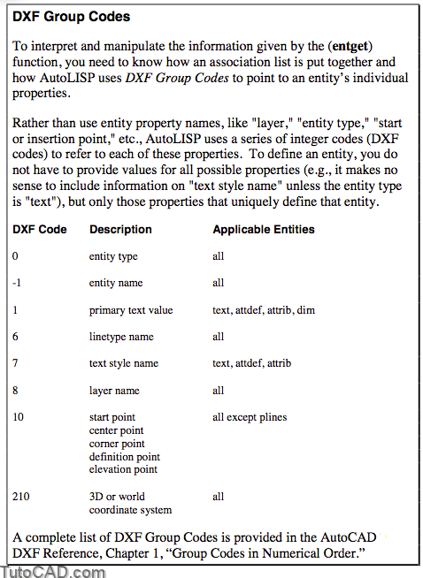
- The initial integer of each sublist refers to a DXF Group Code which correlates to an entity property such as entity name, layer, entity type, endpoints of a line, etc.
- The remaining elements in each sublist refer to the entity property’s unique value for this entity, such as value of the entity name, the value of the layer, etc.
PRACTICE
For each of the entity names that you created in the last practice, find the entity definition list for each and assign them to the symbols “ELIST1” to “ELIST5.” Estimated time for completion: 5 minutes.