How to use Absolute Coordinates
This AutoCAD tutorial will explain how to use absolute coordinate in AutoCAD
You eventually supply at least one point when you use most commands in AutoCAD
- so it is practical to learn basic options for inputting points.
You have already supplied points to commands (perhaps without even realizing it) by just clicking with your left mouse button.
- for example, picking two points when you use Zoom Window is an example of inputting points in AutoCAD.
Other typical prompts for points are shown below.
Specify first point:
Specify next point or [Undo]:
Specify first corner:
Specify opposite corner:
Specify base point:
Every point has a 3D address specified by absolute coordinates.
- this address has three ordinates ( X, Y, Z ) but in 2D drafting the Z ordinate usually has a value of zero.
- in the normal orientation the X axis points to the right, the Y axis points up and the Z axis points directly at you.


X & Y ordinates can be positive or negative values but most two dimensional (2D) drawings are created using positive values.
- the origin ( 0,0 ) can be any point you choose relative to the objects in your drawing and is normally in the lower left corner.
You can supply a coordinate to AutoCAD by pressing your left mouse button when your crosshairs are in the desired position.
- you have already been using this method for commands such as Zoom Window and Line.
- this is the least precise method for supplying points in AutoCAD.
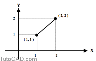
One way to input an absolute coordinate precisely is to enter coordinates using the keyboard as shown in the dialogue below.
Command: LINE ↵
Specify first point: 1,1 ↵
Specify next point or [Undo]: 2,2 ↵
Specify next point or [Undo]: ↵
Command:
Practice using absolute coordinates to supply points
- Launch AutoCAD (if it is not already running). Close all open drawings (if there are drawings open). If AutoCAD was running already then pick File + New to continue.
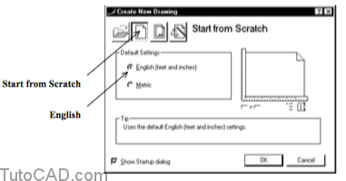
- Select the Start from Scratch button. Select English as the Default Settings and then pick OK to create a new drawing.
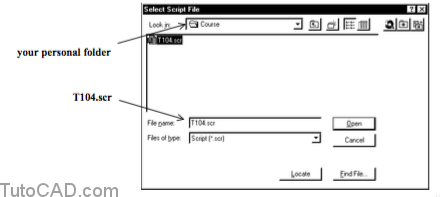
3- Pick Tools + Run Script. Select your personal folder to Look in and select T104.scr as the script File name. Then pick Open to run this script.
There are many different system variables that control coordinate input and drafting tools in AutoCAD 2000.
- you will learn more about some of these settings in this document and they are presented in a logical sequence.
- the script you ran in the last step will ensure that your system is set up to match the behavior described in the exercises.
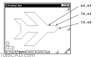
You will create the outline shape illustrated below by using the Line command and typing an absolute coordinate for each vertex.
- each vertex is marked by a filled dot.
- you will begin and end the sequence of LINE objects at the tip of this shape (P1) which is at the coordinates ( 7.5,4.0 ).
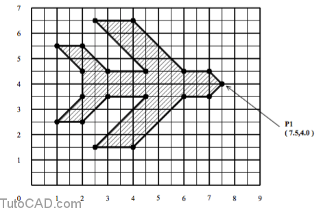
4- Pick Draw + Line and follow the dialogue below to create this outline shape. When you get back to the starting point press <enter> at the prompt for the next point.
Command: _line
Specify first point: 7.5,4.0 ↵
Specify next point or [Undo]: 7.0,4.5 ↵
Specify next point or [Undo]: 6.0,4.5 ↵
(complete the outline shape on your own)