Tracking With Alignment Points
The Object Snap Tracking tool is an alternative to using point filters in earlier AutoCAD versions.
- you can use Object Snap Tracking to pick a point that is generated using one or more alignment points.
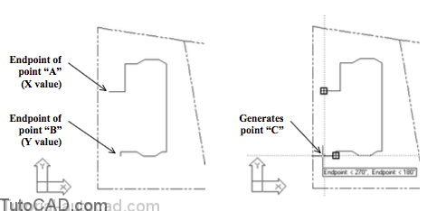
In the simple example below, the desired point “C” could begenerated from the X value of point “A” and the Y value of point “B”
- Object Snap Tracking can also incorporate the power of PolarTracking (that you used in the last exercise)
- so this tool is even more powerful than point filters.
Object Snap Tracking is in effect when the OTRACK status bar button is On.
![]()
You can toggle the current OTRACK status at any time (even when commands are running)
- left-click on the OTRACK status bar button
- press the F11 function key.
- change Object Snap Tracking on Object Snap tab of Dsettings.
Tracking can be an effective alternative to using the From tool (or construction LINEs) for picking points relative to existing objects.
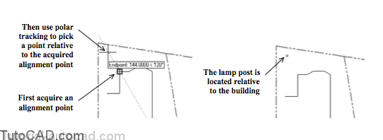
- hold your crosshairs over an osnap marker to acquire it as an alignment point & move your crosshairs to invoke tracking.
- the Polar Tracking vector can constrain your cursor movement and you can pick a precise point relative to the alignment point.
For example, you could create a CIRCLE (to represent a lamp post) with the center at a precise point relative to a corner of a building
- you would use Tracking at the CIRCLE center prompt.
Command: CIRCLE↵
Specify center point for circle or [3P/2P/Ttr (tan tan radius)]: (use tracking)
Specify radius of circle or [Diameter] <3.0000>: 6 ↵
Command:
You will probably acquire unwanted alignment points by accident.
- hold your crosshairs over any currently acquired alignment point to clear (remove) that alignment point.
You can manually acquire new alignment points by entering TT at the keyboard when AutoCAD prompts for points.
- you can also pick the Temporary Tracking Point button in the Object Snap toolbar.
- these temporary tracking points do not have to reside on osnap points which lets you track to any point in your drawing.
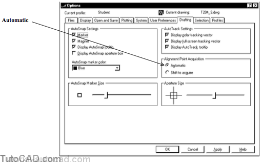
Alignment Points are acquired Automatically by default when OSNAP and OTRACK are On
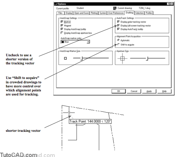
- however, when your drawings are crowded you may want to Shift to acquire instead.
- then you must explicitly hold your crosshairs over an object snap marker & press <Shift> to acquire an alignment point.
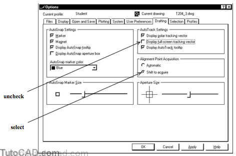
- use Options and select the Drafting tab to make this change.
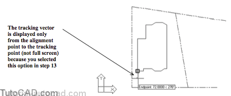
If you are distracted by the full screen tracking vector you can turn this off by unchecking the Display full-screen tracking vector box
then the tracking vector is displayed only between the last point and your tracking point (near the crosshairs).
PRACTICE WITH TRACKING
» 1) Continue in the same drawing file as the previous exercise (or Open the T204_3.dwg in your personal folder).
» 2) Right-click on the OTRACK status bar button and select Settings from the shortcut menu. Check the Object Snap Tracking On box and then pick Options to continue.

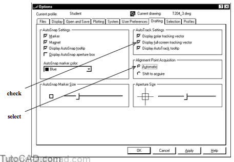
3) Verify that the Alignment Point Acquisition is set to Automatic and the other settings match the ones shown below then pick OK to return and OK to complete Dsettings.
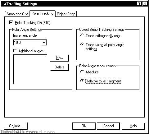
4) Right-click on POLAR and pick Settings from the shortcut menu and verify the settings match the following figure. Then pick OK.
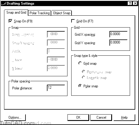
5) Right-click on SNAP and pick Settings from the shortcut menu and verify the settings match the following figure. Then pick OK.
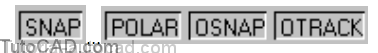
6) As a final check before you continue verify that the following status bar settings are On. (GRID & ORTHO should be Off)
7) Make FOUNDATION the current Layer.
![]()
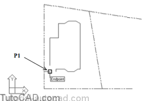
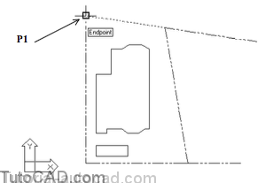
8) Pick Draw + Line and hold your crosshairs over the Endpoint near P1 and left-click to use this point.
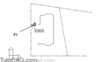
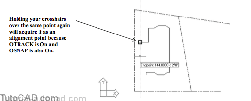
9) Move your crosshairs over the same P1 point until you see the AutoSnap Endpoint marker again (but do not pick this point) and then move your crosshairs away to acquire it as an Alignment point.
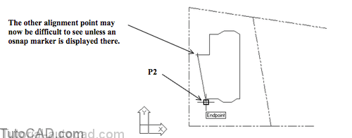
10) Now hold your crosshairs over the osnap Endpoint at the bottom of the small vertical LINE near P2 to acquire this point as an Alignment point (do NOT left-click on it).
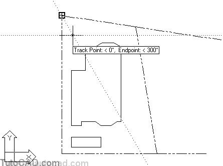
11) Move your crosshairs around and observe how you can select many different points using the existing Polar Tracking settings. When you see two perpendicular tracking vectors as shown below, left-click to use that point for the second point of the Line command.

12) Move your crosshairs to the Endpoint osnap at the bottom of the small vertical LINE near P1 again and left-click to use this point. Then press <enter> to complete the Line.

In earlier AutoCAD Releases these last two LINES could have been created using point filters (but with extra effort).
- more menu picks or extra typing at the keyboard would have been required to achieve the same results.
Using point filters are only practical if the new LINEs are parallel to the X & Y directions of the current UCS.
- whereas Tracking techniques are much easier (and graphical) and can be used in all Polar Tracking directions.
13) Pick Tools + Options and select the Drafting tab. Select Shift to acquire for Alignment Point Acquisition & uncheck the Display full-screen tracking vector box. Then pick OK.
14) Pick Draw + Line and hold your crosshairs over the Endpoint osnap marker near P1 at the lower left corner of the building and press the <Shift> key to acquire this Alignment Point (but do NOT left click on it).
If you left-click when you see an AutoSnap marker you will use that point at the command prompt.
- you selected Shift to acquire so Alignment points are acquired ONLY if you press <Shift> when an AutoSnap marker appears
- but when Automatic is selected you acquire Alignment points automatically by passing your crosshairs over an object snap.
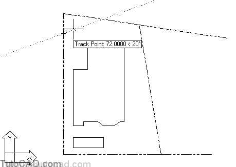
15) Move your crosshairs down until your tooltip says Endpoint: 72.0000 < 270 and then left-click to use that point.
16) Move your crosshairs over the Endpoint osnap near P1 below and press <Shift> to acquire this Alignment point (but do NOT left-click on it).
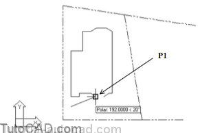
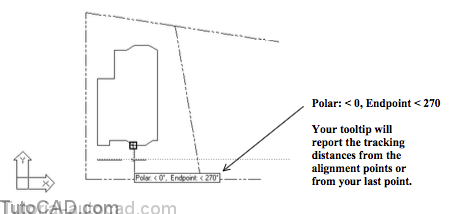
17) Move your crosshairs down until your tooltip says Polar: < 0, Endpoint < 270 and left-click to use that point.
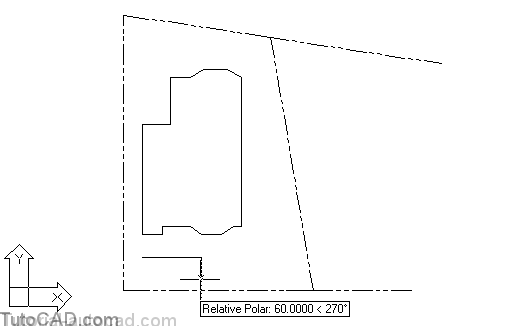
18) Move your crosshairs down until the tooltip says Relative Polar: 60.0000 < 270 and left-click to use this point.
19) Move your crosshairs to the Endpoint osnap marker (back at the point you used to start the Line command) near P1 and press <Shift> to acquire this point (but do not left-click).

20) Move your crosshairs to the location shown below so your tooltip says Endpoint: < 270, Relative Polar: < 270 and then left-click to use this point and enter C at the keyboard to Close the LINE back to the start of the Line command.
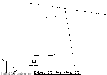
You created this simple rectangular garden plot and it is aligned with the building and has precise dimensions
- but very little keyboard activity was required (except <Shift> to acquire alignment points but this could be Automatic too).
- the steps were broken down to make it easier for you the first time which makes this approach seem more difficult than it is.
You used several Polar Tracking features (and settings that were made in earlier exercises).
- the Tracking tool can be used to align new and existing objects with very flexible options (not just in orthogonal directions).

21) Pick Tools + Options and select the Drafting tab. Select Automatic for Alignment Point Acquisition & check the Display full-screen tracking vector box. Then pick OK.
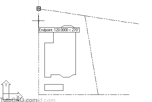
22) Pick Draw + Circle + Center,Diameter and when you are prompted to Specify center point for circle hold your cursor over the Endpoint osnap in the upper left corner of the lot near P1 to acquire this point as an Alignment point (but do not left-click on it).
23) Move your cursor down until your tooltip says Endpoint: 120.0000 < 270 and enter TT at the keyboard (or pick the Temporary Tracking toolbar button) and left-click to use this point as a Temporary Tracking point.
You can manually use Temporary Tracking Points that are NOT on Object Snap points.
- now one of your Alignment points is precisely 120 inches from the Endpoint of the property LINE
The new alignment point is NOT on an Object Snap point.
- you were able to pick this point precisely using Polar Trackingbecause you have Polar Snap set and Snap is On.
24) Move your crosshairs around and observe how your temporary tracking point is used together with the first tracking point but do not pick any points yet.
25) Hold your crosshairs above the Endpoint osnap Alignment point so this point is no longer an Alignment point, Then move your crosshairs around and observe how the temporary tracking point is now the only Alignment point. (Do not pick any points yet and do not to acquire other alignment points.)
You can continue to Track using the Polar Tracking (or other) tools to acquire Alignment points using Temporary Tracking points
- these points do not have to lie on object snaps
- and you can use direct distance entry when the desired points are not on snap points (multiples of your snap increments.)
28) Hold your crosshairs over the Endpoint osnap marker near P1 below (do not left-click) to acquire this Alignment point.

27) Move your crosshairs above this point and left-click to use this point as the CIRCLE center when your tooltip says Track Point: < 0, Endpoint: < 90. Then enter 6 as the CIRCLE diameter to complete Circle.
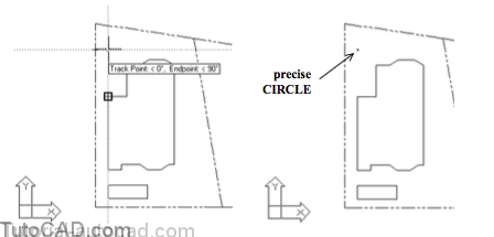
You created this CIRCLE with a location that is precise relative to two different objects in the drawing
- it is 120 inches down from the upper corner of the property line and it is aligned with one edge of the foundation of this building
- however, you did not have to use any point filters at the keyboard to supply the required center point.
» 28) Save your changes to this drawing for the next exercise.