How to use Relative Cartesian Coordinates
Here is how to use relative cartesian coordinates in AutoCAD
It is inefficient to work with absolute coordinates all of the time.
- you are normally more concerned about where a coordinate is relative to other coordinates.
- for example, when you draw a LINE you would want to specify the length of the LINE relative to the starting point.
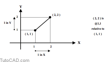
You can specify a point relative to your last point by typing the @ character before you type the X & Y ordinates.
- you normally enter relative coordinates in a command after supplying a specific point.
- when you enter @X,Y it is like saying “from where I am now move by a displacement of X,Y ”.
- the X and Y ordinates can be positive or negative values.
For example, you could draw the LINE below by using the command
Command: LINE ↵
Specify first point: 1,1 ↵
Specify next point or [Undo]: @1,1↵
Specify next point or [Undo]: ↵
Command:
Practice using relative coordinates in AutoCAD
- Close the drawing from the previous exercise if it is open.
- Pick File + New and pick the Start from Scratch button. Select English as the Default Settings & pick OK.
You will create the outline shape illustrated below by using the Line command with relative coordinates this time.
- you will begin and end the sequence of LINE objects at the point near P1 which is at the ( 1.0, 2.5 ) coordinates.
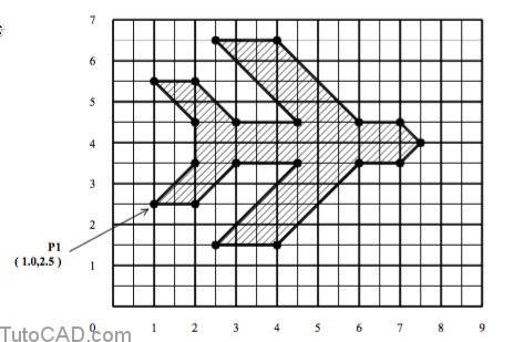
3- Pick Draw + Line and follow the dialogue below to create the outline shape shown above using relative coordinates for all points except the starting point. When you return to P1 you can press <enter> to complete the Line command.
Command: _line
Specify first point: 1,2.5 ↵
Specify next point or [Undo]: @1,0↵
Specify next point or [Undo]: @1,1↵
Specify next point or [Close/Undo]: @1.5,0 ↵
Specify next point or [Close/Undo]: @–2, –2 ↵
(complete the outline shape on your own)