How to make New Drawings From Templates
This tutorial is for to explain how to make a new drawing from templates
You were able to quickly set up drawings in the previous exercise after creating a New drawing from scratch
- but you did not complete the setup by adding layers, dimension styles, text styles and adjusting other preferences.
- these additional steps can be time consuming to repeat every time you start a new drawing.
One way to save time is to Saveas a drawing that has already been completely set up as a template file.
- template files are identical to drawing files except they have a .dwt file name extension (instead of the normal .dwg extension).
- to create a new template file you simply select AutoCAD Drawing Template File (*.dwt) as the Save as type.
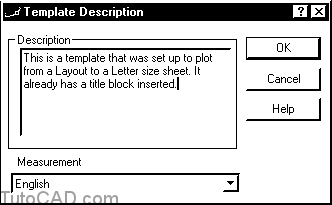
- you can also include an optional description to help you remember what the template is for later on.

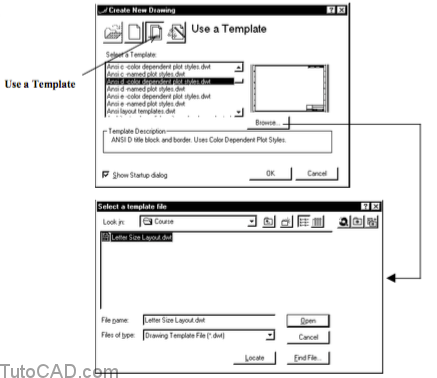
You can Use a Template to create a New drawing and the new drawing will be exactly like the template drawing.
- you can select one of the template files listed in the Select a Template list or pick Browse to look in other folders.


AutoCAD is supplied with many template files already created and they are stored in the Template folder by default.
- the template files supplied with AutoCAD are set up primarily to Plot from a Layout tab
- a plot device is not selected (Plot device is None) so you must select a device before you can Plot or even Preview a plot.
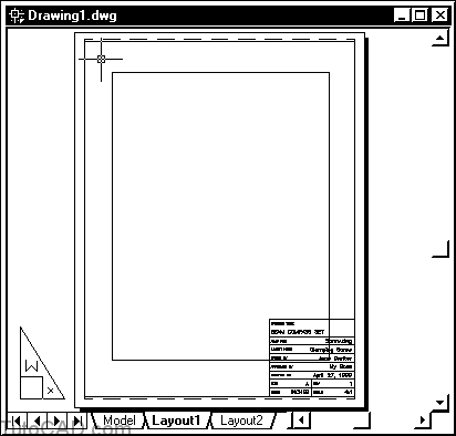
- Layouts normally already include a basic title block and some templates include several tabs with different title block sizes.
- Layout names are normally changed (from Layout1 or Layout2) to appropriate names.
- supplied templates use specific units and drafting standards (e.g. ANSI for drawings in inches & ISO for drawings in mm).
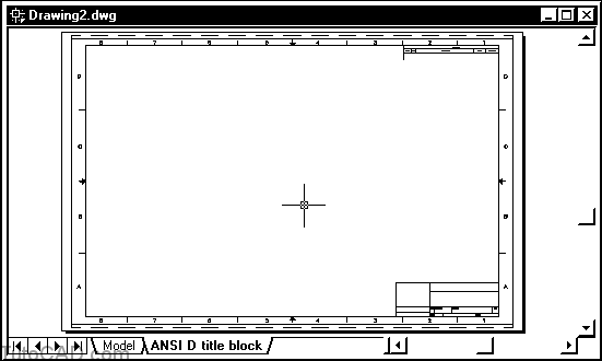
(Example drawing created from a supplied template designed for a D size ANSI sheet.)
Templates supplied with AutoCAD are a good starting point to create your own custom templates
- but you will probably want to add your own layers, dimension styles, text styles & customize title blocks to suit your application.
If you use these supplied template files you should make sure you select a template that uses the plot style behavior you plan to use.
- you can use named plot styles or color dependent plot styles but you cannot change this behavior after a drawing is created.
- you will learn more about plot style behavior later in the course.
Practice creating & using template files
- Continue with the Screw2.dwg drawing you created in the previous exercise.
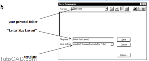
- Pick File + Save As and change the Save as type to AutoCAD Drawing Template (*.dwt). Enter Letter Size Layout as the File name. Select your personal folder as the Save in location and pick Save to continue.
3- Enter a description of your choice or use the example shown below and pick OK.
4- Pick File + Close to close the template.
5- Pick File + New and select Use a Template. Then pick the Browse button and change the Look in location to your personal folder. Select the Letter Size Layout template you just created and pick Open to continue.
The new drawing is identical to the drawing (Screw2.dwg) you used to create the template file but it is now called “Drawing#.dwg”.
You can give it a name of your choice the first time you save the drawing.
6- Pick File + Save and enter Screw3.dwg as the new File name and use your personal folder as the Save in location. Then pick the Save button to complete the command.
7- Pick File + Close to close this new drawing file.
8- Pick File + New and select Use a Template. Scroll down the list and select the Architectural, english units-color dependent plot style template and pick OK.

Most of the templates supplied with AutoCAD are created for a specific sheet size.
- some of the templates indicate the sheet size in the template file name (e.g. Ansi e for an E size sheet).
- this template does not include the sheet size in the file name but you see this information in the Template Description area.
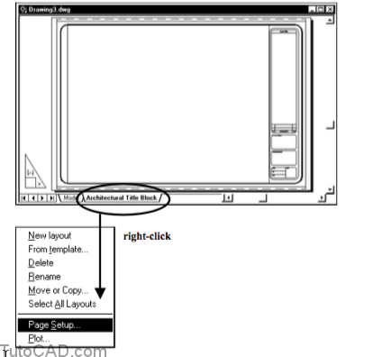
9- Right-click on the Architectural Title Block tab to invoke a shortcut menu and select Page Setup.
10- Use a DesignJet 750.pc3 on the Plot Device tab as Plotter Name & select the Layout Settings tab.

11- Verify that your Layout Settings are as shown below and pick OK.
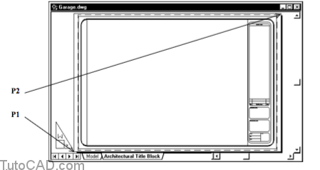
12- Double-click near P1 to switch to model space.

13- Right-click on any toolbar button to invoke a shortcut menu and select the Viewports toolbar (if it is not already checked) to display this toolbar.
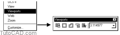
14- Click in the Viewports drop-down list & select the 1/4″ = 1’ scale from the list. Then click on the small x in the upper right corner of the Viewports toolbar to Close it.

15- Pick File + Save and enter Garage.dwg as the File name with your personal folder as the save in location. Then pick the Save button there to complete this command.
16- Double-click near P1 to switch back out to paper space.
17- Pick Tools + Inquiry + Distance and click on two opposite
corners of the sheet by eye near P2 and P3.

Command: ‘_dist
Specify first point: (pick by eye near P2)
Specify second point: (pick by eye near P3)
Distance = 3′-7 5/16″, Angle in XY Plane = 34, Angle from XY Plane = 0
Delta X = 3′-0 1/8″, Delta Y = 1′-11 15/16″, Delta Z = 0′-0″
Command:
The reported distance should be about 3 feet (36 inches) in the X direction and 2 feet (24 inches) in the Y direction.
- the template was set up to use Architectural drawing units so the distance is formatted as feet and inches.
- however, each drawing unit represents one inch
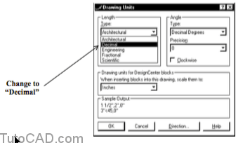
18- Pick Format + Units and change the Length Type to Decimal and pick OK to continue.
19- Pick Tools + Inquiry + Distance and click on two opposite corners of the sheet by eye near P1 and P2.
Command: ‘_dist
Specify first point: (pick by eye near P1)
Specify second point: (pick by eye near P2)
Distance = 43.2312, Angle in XY Plane = 34, Angle from XY Plane = 0
Delta X = 35.9623, Delta Y = 23.9928, Delta Z = 0.0000
Command:
You do not change the size of objects when you change your drawing unit length type.
- you changed from the Architectural type to the Decimal type but the distance between sheet corners should still be the same.
- the reported distance should be about 36 drawing units (inches) in the X direction & 24 drawing units (inches) in Y direction.
There are several different drawing unit length types to choose from.
- the following table shows examples for the same distance of 15.5 drawing units formatted with each type.
- you can change the unit length type at any time without changing the size of objects in the drawing.

Settings changed using the Units command will NOT have an effect on the way dimension objects appear.
- you control the format for dimension objects using dimension styles and you will learn more about that later in the course.20- Pick File + Save to update the changes to Garage.dwg21- Pick File + Close to close the Garage.dwg drawing.