How to use Automatic Object Snap Tracking
Here is a free course how to use Automatic Object Snap Tracking in AutoCAD
- You can create temporary LINEs as construction objects when you draw in AutoCAD.
- for example, you can transfer features between views by creating LINEs and then using Trim to make them the correct length.
- The Object Snap Tracking feature lets you create the desired objects directly without having to perform secondary operations.
- you can make drawings with less effort if you take a moment to master the basics of Object Snap (Automatic) Tracking.
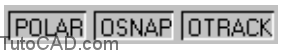
- Object Snap Tracking is in effect when both the OTRACK and OSNAP status bar buttons are On (pushed in).
- You can toggle the current OTRACK status at any time (even when commands are running)
- – left-click on the OTRACK status bar button
- – press the F11 function key.
- – change Object Snap Tracking on Object Snap tab of Dsettings.
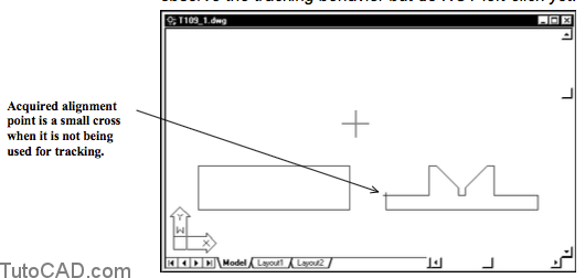
- You acquire a tracking alignment point by holding your crosshairs over an object snap marker at prompts for a point (do NOT left-click).
- -you will see a small cross to mark the acquired alignment point (the osnap marker may also remain displayed).
- -if you acquire the wrong alignment point by mistake you can hold your crosshairs over the acquired point again to remove it.
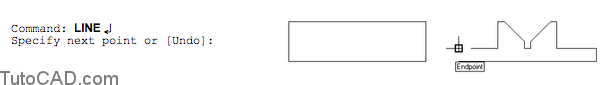
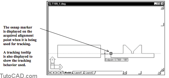
- For example, you could invoke Line and then position your crosshairs to invoke the Endpoint tooltip shown below.
- – hold your crosshairs over the osnap marker (without left-clicking) to acquire this as an alignment point.
- – you begin tracking when you move your crosshairs away from the acquired alignment point.
- You normally use Tracking with other drafting tools and tracking behavior will depend on several factors, such as
- – the object(s) used to acquire tracking alignment points – running osnaps in effect
- – POLAR settings
- – other drafting settings (Drafting tab of Options)
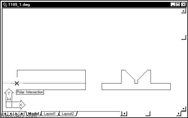
- If POLAR was On and Intersection was set as a running osnap in the example above
- – you could specify the first point of the LINE by invoking the Interesection osnap shown below and then left-clicking.
- The desired object is created by invoking another Intersection osnap & left-clicking to use it as the second point of the LINE.
- Alignment Points are acquired Automatically by default (when OSNAP and OTRACK are On)
- – but when your drawings are crowded you may want to change this setting to use Shift to acquire instead.
- – then you must hold your crosshairs over an object snap marker & press the <Shift> key to acquire the alignment point.
- If you are distracted by the full screen tracking vector you can turn this off by unchecking the Display full-screen tracking vector box
- – then the tracking vector is displayed only between the last point and your tracking point (near the crosshairs).

Practice: using Object Snap Tracking tutorial in AutoCAD
- Launch AutoCAD (if it is not already running). Close all open drawings (if there are drawings open).
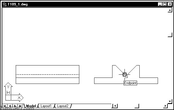
- Open the T109_1.dwg drawing in your personal folder.
- Pick Tools + Run Script. Select your personal folder to Look in and select T109.scr as the script File name. Then pick the Open button to run this script. This sets drafting tools to match the behavior described in the exercises.
- Left-click on POLAR, OSNAP and OTRACK status bar buttons to toggle these tools On.
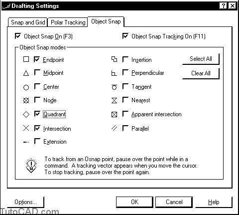
- Right-click on the OSNAP status bar button to invoke a shortcut & select Settings. Observe the running osnaps in effect and pick OK to exit Dsettings.
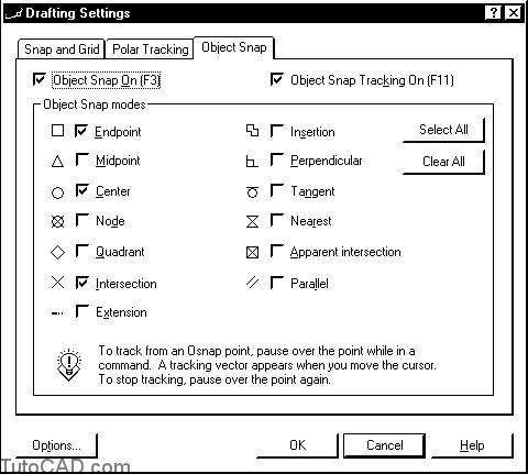
The Tip in this dialogue box is describing Object Snap Tracking.
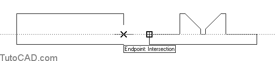
- Pick Draw + Line. Move your crosshairs (do not left-click) above the Endpoint marker shown to acquire it.

- Move your crosshairs to the positions shown below and observe the tracking behavior but do NOT left-click yet.
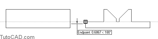
- Move your crosshairs near the edge of the front view so the tracking tooltip says Endpoint: Intersection and then left-click to use this point as the start of the LINE.

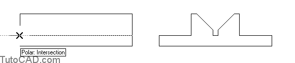
The POLAR tool constrains your tracking vector to move horizontally and this has an impact on the point of Intersection
– this point combines the Y ordinate of the Endpoint with the X ordinate of the vertical LINE in the front view.
- Move your crosshairs to the other side of the front view to invoke the Polar: Intersection tooltip shown below and left-click to use this point as the second point of the LINE. Then press <enter> to terminate Line.
- Drop down the Layer list in the Object Properties toolbar and select Hidden Lines as the new current layer.

Now on your own
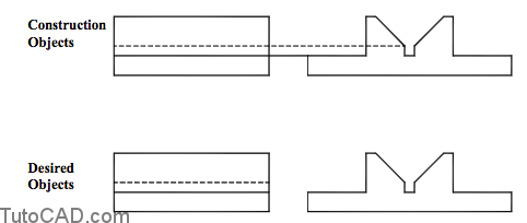
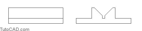
- Use a similar technique to create the hidden LINE shown below using the Endpoint shown in the end view.
- Save the changes to this drawing and Close the file.
More practice?
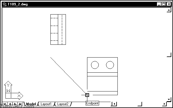
- Open the T109_2.dwg drawing in your personal folder.
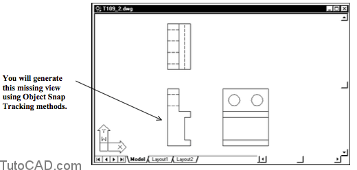
In this exercise you will create the missing front view using ONLY the existing side and top views
– the Object Snap Tracking tool will be used in the same way that a T-Square could be used on a manual drafting table.
- Right-click on the OSNAP status bar button and select Settings from the shortcut.
- Uncheck Center and check Quadrant. Then pick OK.
You will be using the Quadrant osnap to transfer hole edges to the front view later on.
– if the Center running osnap is set it will be selected first which makes this task more difficult.
- Pick Draw + Line & hold your crosshairs over the Endpoint osnap shown below without left-clicking to acquire it as an alignment point.

- Hold your crosshairs over the Endpoint osnap marker below without left-click to acquire it as another alignment point.

- Move your crosshairs to the location shown below to invoke a tracking tooltip that says Endpoint < 270, Endpoint < 180 and left-click to use this as the start of the LINE.
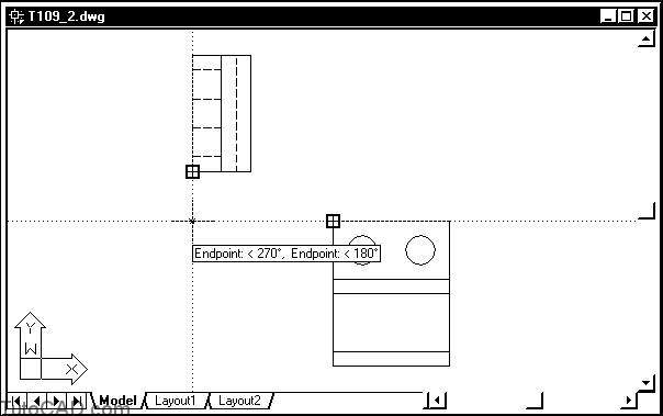
You are about to trace the outline edge of the front view and this start point is the upper left corner for this view.
– you started this LINE at the required point without having to create any construction lines first.
- Hold your crosshairs over the Endpoint osnap shown below to acquire it as an alignment point.
- Move your crosshairs directly below the start of the LINE to invoke the Polar < 270, Endpoint < 180 tracking tooltip then left-click to use this as the second point of the LINE.
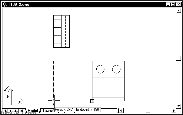
The tracking tooltip indicates which points are used for tracking and the angles from those points.
- Use a similar technique to draw LINE segments around this front view such that they are aligned with the corresponding features in the other two views. The final outline shape is illustrated on the following page.

- Drop down the Layer list in the Object Properties toolbar and select Hidden Lines as the new current layer.
- Create the hidden lines for the holes in the front view using Quadrant osnaps and Object Snap Tracking techniques to complete this drawing view.
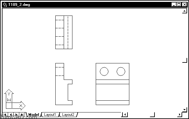
You created this view without having to enter any distances or coordinates at the keyboard.
- Save the changes to this drawing and Close the file.