Backgrounds & Landscapes in 3D drawing
Use Background to set the background of your rendered image.
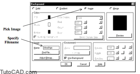
- you can use a Solid color or a Gradient of varying colors
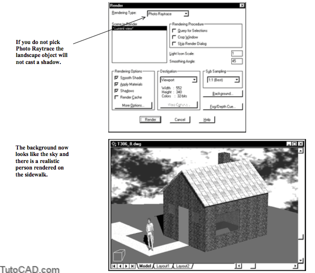
- or use a bitmap Image file (e.g. cloud.tga) to make your renderings appear more realistic (e.g. the sky for a 3D house)
- or select Merge to use the current AutoCAD display as the background for the rendering.
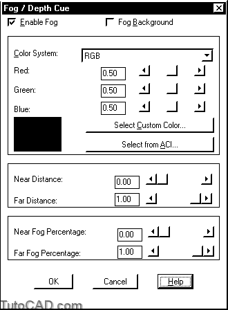
Fog lets you gradually mask objects that are further away & you can control where the fog begins and ends.
- you also control how thick it is at the beginning and the end..
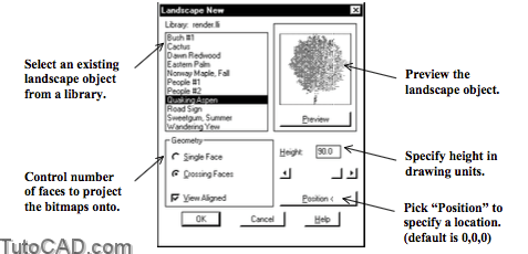
You can model intricate objects (like trees or people) efficiently & realistically as landscape objects using the Lsnew command.
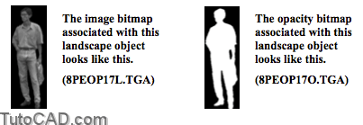
- special bitmap images (2 per object) are projected onto single or crossed faces to yield realistic images with minimal effort.
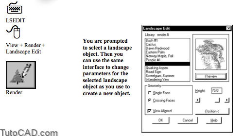
- Use Lsedit to modify parameters of landscape objects that you have already inserted into a model.
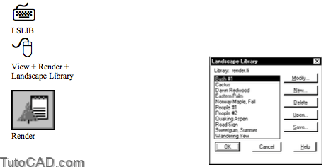
- Use Lslib to create & manage your own custom landscape objects. – making your own landscape objects is complicated so AutoCAD already has a few typical objects that are ready to use.
PRACTICE WORKING WITH BACKGROUNDS AND LANDSCAPE OBJECTS
1) Open the T306_8.dwg file in your personal folder.
2) Pick View + Render + Background. Select Image then typeCLOUD.TGA as the Name. Pick OK.

3) Pick View + 3D Orbit. Right-click in the drawing area to invoke a shortcut. Pick Projection then select Parallel. Press <Esc> to terminate 3dorbit.
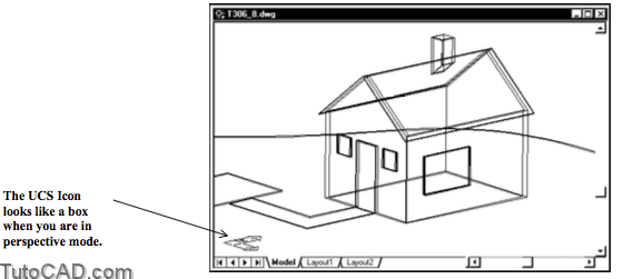
You are about to create a new landscape object and you must specify a location point.
- you are limited to typing coordinates for points when you are in perspective projection mode which can be inconvenient.
- in parallel projection you can pick points on-screen.
4) Make sure OSNAP & POLAR are Off in the status bar.
5) Make Grass the current Layer.
![]()
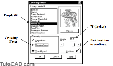
6) Pick View + Render + Landscape New. Select People#2. Change the height to 75. Select Crossing Faces. Then pick the Position button to continue.
7) Move your crosshairs to a point on the sidewalk near P1 and left-click to use this approximate point as the location. Then pick OK to complete the Lsnew command.
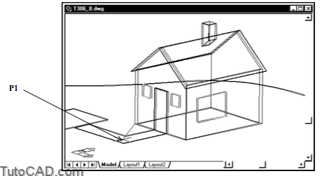
The default position is (0,0,0) and this is the anchor point for the cursor rubber band when AutoCAD prompts for a new location.
- the Z ordinate will be 0 (the point will be on the XY plane of the current UCS) if you do not use an osnap.
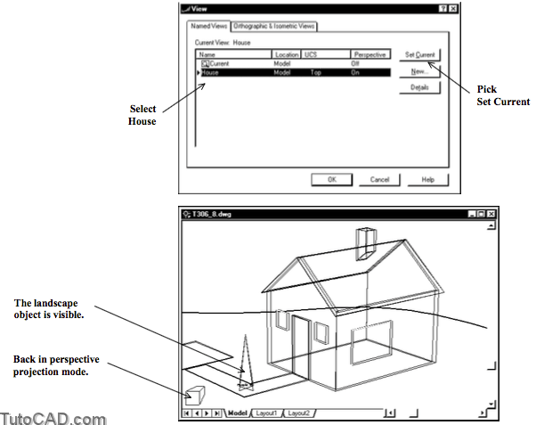
8) Pick View + Named Views. Select House and pick Set Current. Then pick OK.
When you select Crossing Faces for the landscape object the bitmaps are projected onto two perpendicular faces
- so if you change your point of view the landscape will still be rendered appropriately.
- if you use a Single Face you must be sure that the face is View Aligned or you may not see that object when you Render.
- landscape objects have image bitmaps & opacity bitmaps associated with them (stored in the Textures folder by default).
9) Pick View + Render + Render. Change the rendering type to Photo Raytrace. Then pick the Render button with all other settings as shown.
More practice?
10) Add some trees supplied as landscape objects along the horizon behind the house using a similar technique.
11) Render the perspective view with the new trees.
12) Save your changes to the drawing.
More Practice
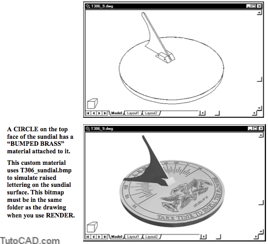
Open the T306_9.dwg file in your personal folder.
- Render this sundial model for various different times of the day by editing the SUN light and using the Sun Angle Calculator.
- the location of the SUN light has already been set up specifically for this sundial model (change ONLY the time of day).
A T306.avi video clip is an animated series of renderings for this model over a 12 hour period (6:00AM to 6:00PM).
- in rendered animations, objects can move, the camera (view) can move and (as in this project) lights can move.