Types Of 3D Models
You can model real world objects in AutoCAD using a variety of different object types.
- 3D models can include surface models, solid models or custom objects from other applications.
- your task is to choose a model type that best meets your needs and you might even use all types of models in the same project.
Surface Models In AutoCAD
Some industries are well suited to basic surfaces that can be created entirely inside AutoCAD (without additional application software).
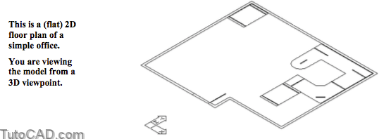
- for example, 2D floor plans can normally be quickly converted to 3D surface models for presentation purposes.
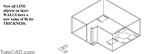
- in some cases changing the THICKNESS property of wall LINEs (to match wall height) is the main 2D to 3D conversion task.
Use the Properties tool to change the THICKNESS property of selected 2D objects.
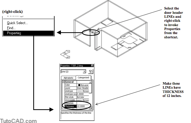
- you can select objects when no command is running then right- click in the drawing area to invoke a shortcut & pick Properties
- or you can invoke Properties explicitly and use the Quick Select tool to automatically find objects that match specific criteria.
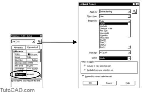
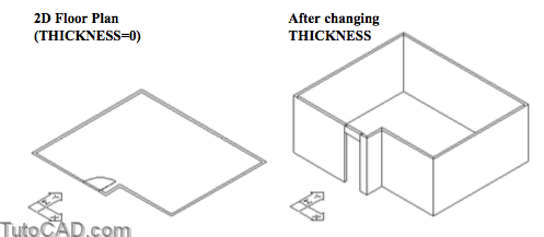
For example, the simple 2D floor plan below could be converted to 3D by changing the THICKNESS of wall LINEs to 96 inches.
- door header LINEs could be moved above the floor by 84 inches (height of the door) and the THICKNESS set to 12 inches.
THICKNESS is always applied in the direction of positive Z for the UCS that was current when the 2D object was created.
- for some 2D objects (e.g. CIRCLEs) it will be obvious what the XY plane was when the 2D object was created.
- however, LINEs can be created in any plane so it will not always be obvious what the current UCS was when a LINE was created.
- you can use positive or negative values for THICKNESS.
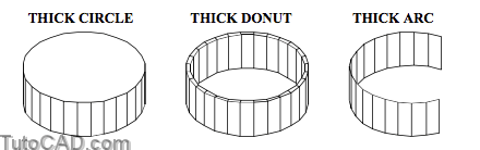
CIRCLEs with THICKNESS are like solid cylinders because they have a top, bottom and side surfaces.
- even CIRCLEs with zero THICKNESS are opaque and can Hide objects behind them.
- DONUTs (circular LWPOLYLINEs with width) have inner, outer, top and bottom surfaces like a section of a pipe.
- ARCs with THICKNESS do not have a top or bottom surface.
When LWPOLYLINEs have both THICKNESS and WIDTH you will have surfaces on all sides of the object.
- you can specify Width of LWPOLYLINEs when they are created with Pline or when you edit them with Pedit.
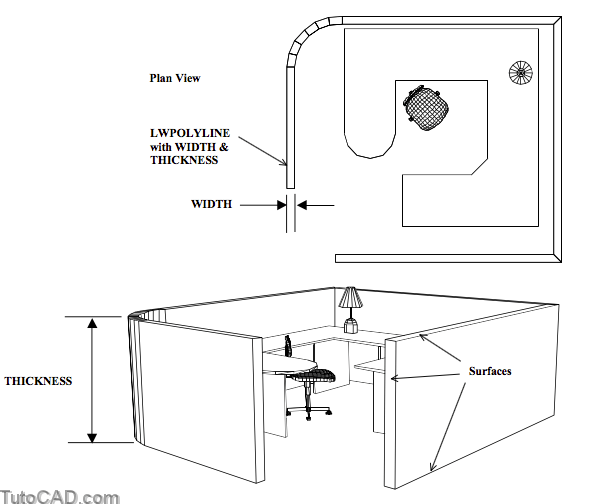
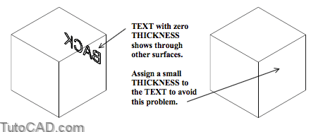
TEXT & MTEXT of zero THICKNESS is not hidden by other surfaces but you can assign a small THICKNESS (e.g. 0.001) to avoid this.
You have already seen how to convert a closed LWPOLYLINE into a REGION object using the Region command.
- REGIONs are practical 2D surface objects that can be created with 2D shapes that you can draw in AutoCAD.
- you can even Subtract internal REGIONs from a larger REGION to create a new REGION with holes in it.
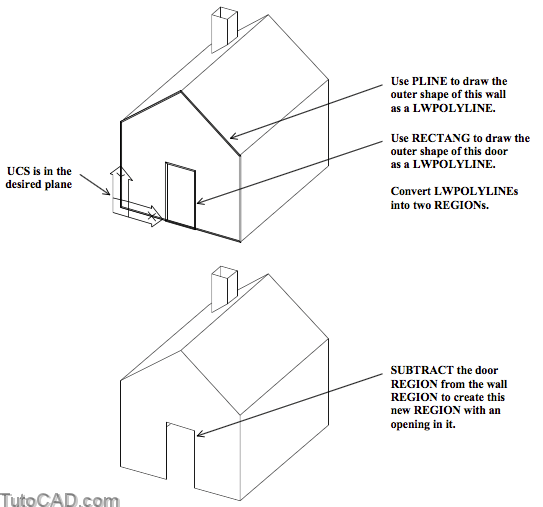
For example, you could create all of the outer surfaces for the simple house model below using REGION objects.
- you would orient your UCS in appropriate planes and create LWPOLYLINEs using the Pline command.
- any openings (e.g. doors or windows) could be created with LWPOLYLINEs using the Rectang command.
- then these inner LWPOLYLINEs could be converted to REGIONs and subtracted from the main REGION for that side of the house.
You can approximate free form surfaces using polygon meshes and AutoCAD lists these objects as POLYLINEs.
- these objects may be practical for visualization purposes but cannot be treated as precise surface models in most cases.
- if you must model free form surfaces precisely you should consider using the Mechanical Desktop application instead.
Meshes are faceted (not true free form surfaces) and you can influence the size of each facet when you create these objects.
- however, you cannot change the resolution of these meshes after they are created
- and you cannot snap to centers which limits the usefulness of polygon mesh objects.
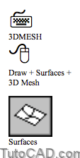
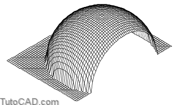
The 3dmesh command creates rectangular polygon meshes (in X & Y) with variable positions in the Z direction.
- this command is normally used in programs (e.g. grafun.lsp Autodesk sample) that calculate values for X,Y & Z automatically.
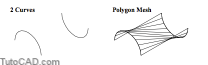
The Rulesurf command creates polygon meshes as ruled surfaces between two curves oriented in 3D space.
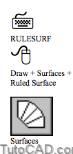
- it is as if you dragged a steel ruler across two curves in 3D to sculpt clay from a model & reveal the “ruled” surface underneath.
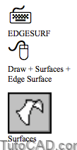
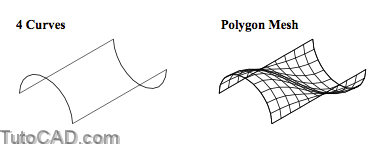
The Edgesurf command creates polygon meshes using 4 curves that form an enclosed path.
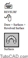
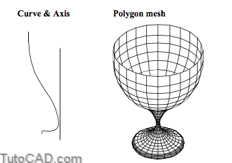
The Revsurf command creates polygon meshes by revolving a curve about an axis LINE.
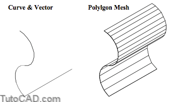
The Tabsurf command is like assigning THICKNESS to a 2D curve but the end result is a polygon mesh instead
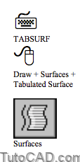
- you select a path curve and a vector direction LINE which determines the direction & distance to generate the mesh.
You can also create primitive shapes as polygon mesh objects by selecting a shape from the 3D Objects dialogue box.

- these correspond to the same objects that can be created using the 3d command at the command line.

Solid Models In AutoCAD
Solid models are normally much easier to create & manage than surface models
- so you will probably prefer to create solid models rather than surface models most of the time
- with the exception of some very basic surfaces (like wall LINEs that are assigned THICKNESS in architectural plans).
Solids automatically acquire a mesh surface when required (e.g. to Shade or Render a model) for presentation purposes
- but the true geometrical forms (e.g. hole centers) are retained so you can snap to precise points using standard osnaps.
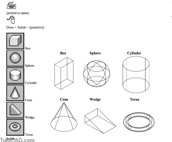
You can create six SOLID primitives using the AutoCAD command of the same name as the desired primitive.
- these primitives are oriented relative to the drawing plane of the current UCS
- so you can define an appropriate UCS before creating a new UCS to orient new primitives as desired in 3D.
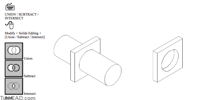
SOLIDS can be combined using Union, Subtract and Intersect (same boolean commands for REGIONs in 2D are listed on page 6)
- for example, you can Subtract a cylinder SOLID from a box SOLID to create a hole in a new SOLID.
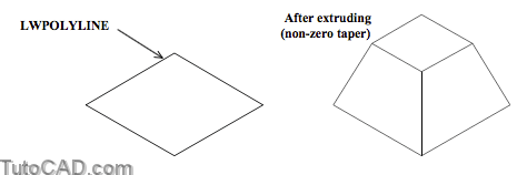
The Extrude command is very practical in solid modeling because you can create many common forms this way.
- you can Extrude REGIONs, LWPOLYLINEs or CIRCLEs in a straight line that is perpendicular to the plane of the 2D object
- or Extrude these 2D objects along a path instead.
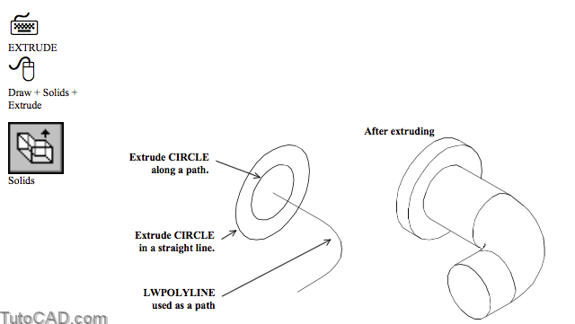
– you can also Extrude using a taper angle which is practical for fabrication methods that require draft angles on surfaces.
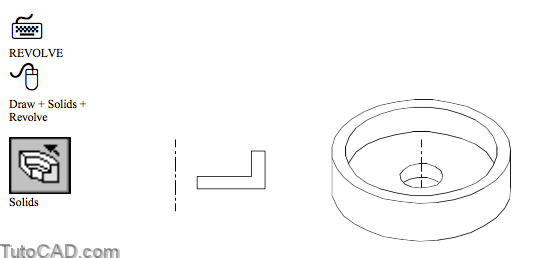
You can Revolve REGIONs, LWPOLYLINEs or CIRCLEs to create a SOLID of revolution (e.g. parts to be machined on a lathe).
- the angle for revolution does not have to be a full 360 degrees.
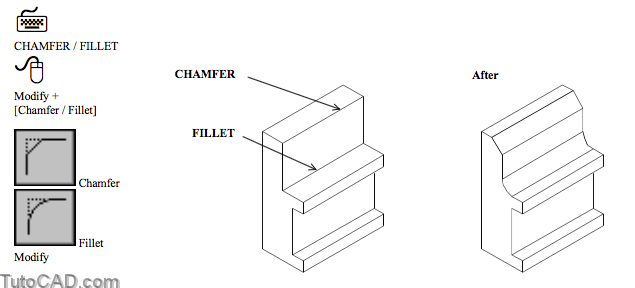
- You can use the same Chamfer & Fillet commands to edit SOLIDs as you use on 2D objects.
Many solids editing tools are specific to SOLIDs.
- these tools range from changing the color of faces & edges (for clarity) to tools for making thin shells from existing SOLIDS.
- you will learn more about these tools in the Creating SolidModels
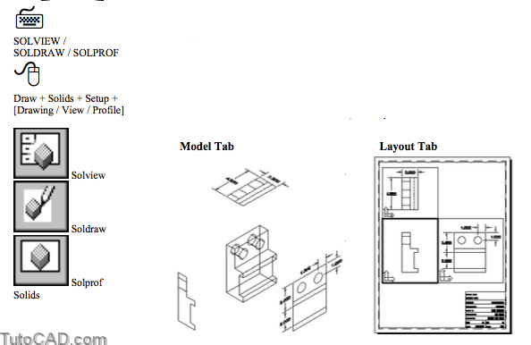
2D drawings can be generated automatically from SOLIDs usingSoldraw & Solprof if you set up a layout using Solview.
- you must add your own dimensions but layers are automatically set up to be visible only in appropriate viewports.
- you will learn more about these tools in the Generating 2DDrawings From Solid Models
Other Model Types
You do not have to create all of your 3D models in AutoCAD 2000 using the tools described so far in this document.
- One alternative is to use an existing library of models for components that someone else has already created.
- this would let you make impressive 3D models with only a limited amount of 3D modeling knowledge required.
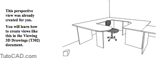
- for example, you could create simple floor plans and insert 3D symbols for the complicated objects (like chairs, desks & lamps)
Another alternative is to use application programs that are written to run inside AutoCAD for a specific industry.
- for example, you could use Mechanical Desktop to create mechanical components in 3D
- you could use Architectural Desktop to create buildings in 3D.
Some applications use native AutoCAD objects that can be edited freely using AutoCAD alone
- whereas other applications create custom objects that can only be edited if you have the application that created them.
- custom objects may not even be visible in AutoCAD 2000 if the application used to create the objects is not installed.
You may get a warning message if you use AutoCAD 2000 to open drawings that contain custom objects (not made in AutoCAD 2000).
- AutoCAD may tell you “proxy objects and proxy entities may yield unexpected results during certain operations”
Some applications have object enablers that let other AutoCAD users (who do not have the application) work with these drawings.
- these object enablers are normally free (for download) to help other AutoCAD 2000 users at least work with these objects.
- however, you will normally need the entire application if you want to modify the objects.
PRACTICE WORKING WITH DIFFERENT TYPES OF 3D MODELS
» 1) Close the drawing from the previous exercise if it is open.
» 2) Open the T301_2.dwg drawing in your personal folder.
3) Pick Tools + Properties to invoke this tool (if it is not already displayed on your screen).
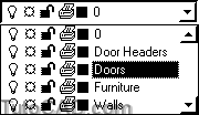
4) Pick the Quick Select button in the Properties window. Change the Object Type to Line and select Layer for Properties. The Operator should be = Equals and the Value should be Walls. Pick OK to select all objects matching these criterion and return to the Properties window. In the General category, type 96 as the new Thickness value. Then select the word Thickness for this change to take place.

5) Pick View + Zoom + Extents to clear the selected objects then Close the Properties tool.
» 6) Pick Modify + Move and select the two door header LINEs (in the open doorway) then press <enter> to continue. Enter 0,0,84 as the displacement and press <enter> at the second prompt to move these LINEs 84 inches above the floor.
» 7) Select the same two LINEs when no command is running to highlight them. Then right-click in the drawing area to invoke a shortcut and select Properties. Using a similar technique as for the Walls LINEs, change the THICKNESS of these two LINEs to 12. Then press <Esc> twice to clear the selected objects & dismiss Properties (if you wish).
8) Make Doors the current layer.
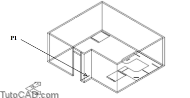
9) Pick Draw + Solids + Extrude. Select the rectangular LWPOLYLINE (outline shape for the base of the door) near P1 and press <enter> to continue. Enter a value of 84 as the height & press <enter> to use a value of 0 for taper.
10) Make Furniture the current layer.
11) Use a similar technique to Extrude the 3 LWPOLYLINE outlines for desks near P2, P3 and P4. Use a value of 1 for the height of these desk tops and a value of 0 for taper.
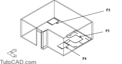
12) Pick Modify + Move. Select the new SOLIDs near P2, P3 and P4 and press <enter> to continue. Enter a displacement of 0,0,30 and press <enter> at the second prompt to move these 3 desk tops 30 inches above the floor.
13) Now Extrude all of the supports for the desk tops by 30 inches so the desk tops are not floating in mid air. (There are a total of 10 rectangular LWPOLYINEs already created for these supports).
14) Pick View + 3D Views + Top & verify that the OSNAP status bar button is Off (Left-click on this button if it is On).
15) Pick Insert + Block. Pick the Browse button and navigate to your personal folder. Select the T301_3.dwg drawing and pick the Open button to return to the Insert box. Specify On- screen should be checked for Insertion point & unchecked for the other two parameters. Pick OK then left-click near P1 by eye as the insertion point.

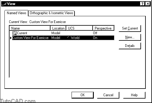
16) Pick View + Named Views. Select the Custom View For Exercise and pick Set Current. Then pick OK.
17) Pick View + Hide.
More practice?
18) Pick View + 3D Views + Top.
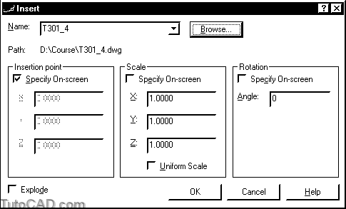
19) Pick Insert + Block. Pick the Browse button and navigate to your personal folder. Select the T301_4.dwg drawing and pick Open to return to the Insert box. Then pick OK to continue and AutoCAD will prompt for the insertion point. You will supply this point in stages using point filters and this process is described on the following page.
20) The OSNAP status bar button should be On. Using the keyboard, type .XY (do not forget to type the period before the XY letters) and press <enter>.
Specify insertion point or [Scale/X/Y/Z/Rotate/PScale/PX/PY/PZ/PRotate]: .XY ↵
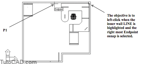
21) Hold your crosshairs over the wall LINE near P1 below and keep pressing the <Tab> key until you see the Endpoint osnap marker shown below. Then left-click to use this point for the X & Y ordinates of the point.
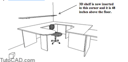
22) AutoCAD will prompt you for the Z value and you can enter 48 to complete all three ordinates for the 3D insertion point of this drawing.
23) Use the Previous option of Zoom to restore the perspective view of the model again.
24) Pick View + Hide.
You used the Endpoint osnap in the top view but it is not obvious whether the osnap was finding the top or bottom of the wall LINE.
- you can use point filters (as in this example), select points from isometric viewpoints or watch the coordinate read-out to be sure.
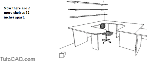
» 25) Pick Modify + Copy. Enter L to select the Last object (the shelf) and press <enter> to continue. Type 0,0,12 as the displacement and press <enter> at the second prompt.
» 26) Repeat the last step.
» 27) Pick View + Hide again.
28) Save the changes to this drawing.
29) Pick View + 3D Orbit. Right-click in the drawing area to invoke a shortcut and pick More. Then pick Continuous Orbit and drag the model slowly (near the center of the screen) to start it spinning slowly on-screen. Try to make it appear that you are slowly flying around the office.
30) Right-click in the drawing area to invoke the shortcut again and pick Shading Modes then select Flat Shaded. Enjoy watching your model revolve around the screen!
31) Press <Esc> to exit this viewing mode.
32) Save the changes and Close the drawing.
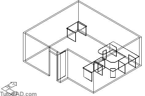
With relatively little effort you were able to quickly create a convincing model of an office with very little 3D knowledge required.
- the chair is comprised of surface meshes (an older 3D symbol that could be made with SOLIDs instead).
- the walls are simple LINEs with appropriate THICKNESS.
- the desks, door & shelves are SOLIDs created from simple LWPOLYLINEs that you probably already know how to create.