Drawing Planes & UCS Icons
Cartesian Coordinates For 3D
You are normally not concerned with the Z axis and Z ordinates are usually zero when you use AutoCAD for 2D drafting & design
- but you can specify Z ordinates other than zero (when AutoCAD prompts for points) to create objects in 3 dimensions.
- by default, the X axis points to the right, the Y axis points up and the Z axis points at you when you face your monitor.
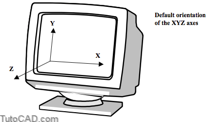
You can view these axes from a different point of view and you can define custom axes at any orientation
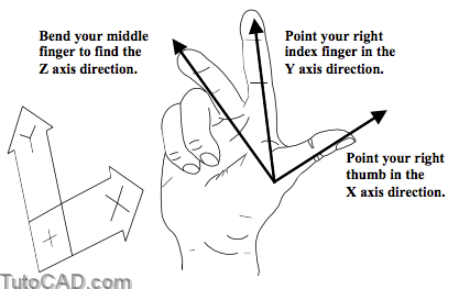
- but the relationship of the Z axis to the X and Y axes will always be the same according to the right hand rule.
Drawing Planes And The UCS
If you do not include Z ordinates when you type coordinates for points, the supplied point is on the drawing plane of the current UCS.
- this drawing plane (also called the construction plane or the XY plane) is normally defined by the X and Y axes.
- when you pick points on screen (without using an osnap) it is the same as typing only X & Y ordinates at the keyboard.
For example, you could draw the 2 LINE objects in 3D as shown below using the command line history shown.
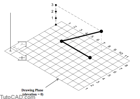
LINE in XY Plane
Command: LINE↵
Specify first point: 3,6↵
Specify next point or [Undo]: 8,6↵
Specify next point or [Undo]: ↵
LINE with different Z ordinates
Command: LINE↵
Specify first point: 3,6↵
Specify next point or [Undo]: 8,8,3↵
Specify next point or [Undo]: ↵
You can use the Elev command to change the elevation of the drawing plane relative to the XY plane of the current UCS.
- for example, if you change the elevation to 5, the Z ordinate will be 5 when you supply only the X and Y ordinates for a point.
- it is less confusing to change the UCS origin rather than changing the elevation (the default elevation is 0).
You can also supply points in 3D using a cylindrical or spherical format for coordinates.
- you can use these formats for any model shapes (not just for cylindrical or spherical models).
- points are relative to the origin (0,0) of the current UCS unless you enter @ before typing cylindrical or spherical formats.
Cylindrical Coordinates
@R<A,Z
The format for relative cylindrical coordinates is @R<A,Z
- where R is the cylinder radius, A is the angle from the X axis andZ is the distance in the Z axis direction.
- this is the same as relative polar coordinates (used in 2D) with a Z ordinate appended at the end.

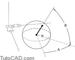
Spherical Coordinates
@R<A<B
The format for spherical coordinates is @R<A<B
- where R is the radius (distance from last point), A is the angle from the X axis and B is the angle from the XY plane.
WCS vs UCS
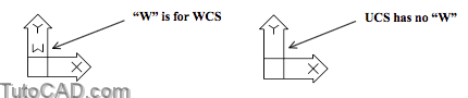
When you start New drawings from scratch you see theWorld Coordinate System (WCS) icon in the following orientation.
- you know it is the WCS when the letter “W” is displayed.
- the letter “W” is not displayed for any other UCS(User Coordinate System).
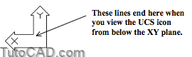
View From Below XY Plane
When you view models from underneath (e.g. the Bottom view) you see only the outline of the UCS icon and the appropriate labels.
- lines that normally cross to form a box in the corner are not displayed from any viewpoint that is under the drawing plane.
View Parallel To The XY Plane
The UCSICON is a box with a broken pencil if you view your model in a direction parallel to the XY plane of the current UCS.
- for example, you will see this icon in the Right view for the WCS.
![]()
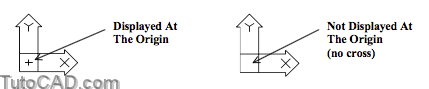
Displayed At The Origin
When the UCS icon is currently displayed at the origin point you will see a small cross inside the UCS icon at this point.
- otherwise, the UCS icon is in the lower left corner of the display and there is no cross in the icon.
Perspective Projection
When projection is Perspective the UCS icon looks like a box viewed in perspective
- you can change projection modes using the right-click shortcut menu when 3dorbit is running.

UCS Icons shown on the previous page (and the perspective icon shown above) are used in the 2D Wireframe setting of Shademode.
- you can use the Shademode command to change settings

- or pick Shading Modes in the right-click shortcut menu when 3dorbit is running to select modes that are NOT 2D Wireframe.

UCS Icon Settings
The UCS icon can clutter your screen and get in your way at times.
- you can toggle the display of the UCS icon On or Off from theSettings tab of the Ucsman dialogue box as required.
You will change the UCS icon settings for all active viewports if youcheck Apply to all active viewports.
- otherwise, any changes will affect only the current viewport.
Check Display at the UCS origin point to display icons at the origin of the current UCS instead of the lower left corner of the display
- if the entire icon will not fit on-screen at the origin point it will be displayed in the lower left corner of the display instead.

In the next exercise you will work with a model that has already been set up to use a UCS that is different than the WCS.
- you will see how important the drawing plane is when you create 2D geometry in 3D.
- you will also practice changing the UCS Icon settings.
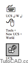
You can return from a UCS to the World Coordinate System(WCS) at any time by using the World option of the Ucs command. – you will use this command option in the next exercise.
PRACTICE WITH 3D COORDINATES AND UCS ICONS
» 1) Launch AutoCAD (if required). Pick File + Open and select the T303_1.dwg drawing file in your personal folder. Close all other drawings (if other drawings are open).
» 2) Pick Tools + Run Script. Select the T303.scr script file in your personal folder and pick the Open button there to run this script. This sets several system variables to match the behavior illustrated in this manual.
» 3) Pick Draw + Rectangle. Left-click on the OSNAP status bar button to turn it On. Invoke the Intersection tooltip shown below for the first corner and left-click to use this point. Then enter @36,84 for the other corner.

You just sketched the outline of a door using a 2D object (LWPOLYLINE) in this simple model of a house.
- you are viewing this model from a non-standard isometric direction (approximately like SE Isometric).
- the Z axis is pointing towards the “Front” of the model.
- you know the current UCS is NOT the WCS because there is no “W” in the UCS icon.
Your first corner point was a full 3D coordinate (X,Y & Z ordinates) because you used an osnap for this point.
- your second point lies on a plane that is parallel to the current UCS XY plane and has the same Z ordinate as the first point.
- 2D objects like this will always be parallel to this drawing plane.
- the Z ordinate is 0 for the rectangle because the first corner is on the XY plane of the current UCS.
»4) Left-click on the POLAR status bar button to turn it On
(if it is Off). Left-click on the OTRACK status bar button to turn it On (if it is Off).
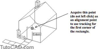
»5) Right-click in the drawing area to invoke a shortcut and select Repeat Rectangle. Hold your crosshairs over the Endpoint marker shown below, without left-clicking, to acquire it as an alignment point when AutoCAD prompts for the first corner point.
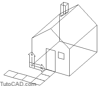
6) Move your cursor to the right to invoke a 0 degree tooltip angle. Type 12 inches as the distance and press <enter> to supply this point as the first corner for the rectangle.

7) Enter @24,–24 for the other corner point (relative to the first corner point).
Drafting tools are as useful in 3D modeling as they are in 2D drafting
- because you can track along the drawing plane (or parallel planes) using the OTRACK and POLAR tools.
- you can use direct distance entry (as in step 6) by invoking the desired tracking vector then typing the desired distance.
- use these tools in planes that are parallel to the XY plane of the current UCS in the same way as you would in 2D drafting.
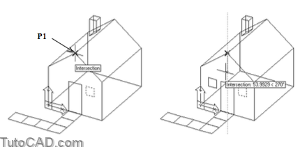
8) Pick Modify + Mirror. Select the last rectangle as the objects to mirror then press <enter> to continue. Invoke the Intersection tooltip near P1 then left-click to use this as the first point of the mirror line. Move your crosshairs downward to invoke the 270 degree tooltip and left-click to use this for the second point of the mirror line. Press <enter> for <N> at the delete the source objects prompt
Familiar 2D edit commands (like Mirror and Rotate) will function the same in 3D as they do in 2D
- the Mirror plane is perpendicular to the XY plane (drawing plane) of the current UCS.
- you Rotate objects about axes that are parallel to the Z axis.
The Rotate3d and Mirror3d commands are more flexible versions of the corresponding commands in 2D
- when you use these 3D commands you are not constrained to these planes and axes in the current UCS.
9) Pick Tools + New UCS + World.

10) Pick Draw + Rectangle. Hold your crosshairs over Endpoint osnap shown below to acquire it (without left- clicking) as an alignment point for tracking. Move your crosshairs to the right to invoke a 0 degree tooltip angle. Type 50 then press <enter> to use this point as the first corner of the rectangle.
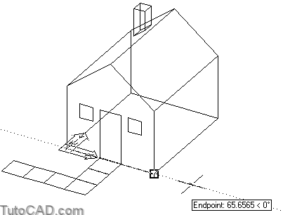
11) Enter @100,100 as the other corner (relative to the first corner point) for this 2D rectangle.

Now the drawing plane is parallel to the base of the house so this 2D rectangle is created in this plane as well.
12) Pick Tools + Named UCS. Select the Settings tab and uncheck the Display at UCS origin point. Then pick OK.

13) Pick View + Shade + Hidden.

» 14) Pick View + 3D Orbit. Right-click in the drawing area to invoke a shortcut. Pick Projection then pick Perspective. Press <enter> to terminate 3dorbit.
» 15) Pick View + Shade + 2D Wireframe.

16) Pick Draw + Rectangle. Pick any point on screen as the first corner and observe the error message on the command line. Then press <Esc> to cancel this command.
Specify first corner point or [Chamfer/Elevation/Fillet/Thickness/Width]: You cannot point within a Perspective view. Change the Projection to Parallel from the 3D Orbit right-click menu.
While the Perspective mode for projection may be desirable for presentations or isometric plots of models
- it is impractical when you create 3D models because you cannot pick points on-screen.
» 17) Pick View + 3D Orbit. Right-click in the drawing area to invoke a shortcut. Pick Projection then pick Parallel. Press <enter> to terminate 3dorbit.
» 18) Save the changes to this drawing and Close the file.