3D Operations
3D Operations
You can manipulate 3D objects using the same familiar commands that you already use in 2D drawings
- such as Move, Copy, Array, Rotate & Mirror
- but Array, Rotate & Mirror are relative to the XY plane of the current UCS (which is not always practical in 3D modeling)
- and Array only creates a 2 dimensional array.
You can use 3D commands to free yourself from the XY plane of the current UCS and to create 3D arrays instead.
- these commands include Rotate3d, Mirror3d, 3darray & Align (in the Modify + 3D Operation pulldown menu).
Use Rotate3d to rotate objects about any axis in 3D by picking two points for the desired axis.
- there are other options for defining the axis but the (default) 2 points option is normally sufficient.
You can use another form of the right hand rule to determine the positive direction of rotation about an axis.
- in 2D the Rotate command revolves objects about an axis that is parallel to the Z axis of the current UCS.
- but when you use Rotate3d you can pick 2 points (from start to end) to define any axis for rotation.
- point your right hand thumb in this direction and your fingers naturally curl in the direction of positive rotation.

You can use the Mirror3d command to create new objects that are mirrored about a specified plane.

- in 2D the Mirror plane is always perpendicular to the XY plane of the current UCS (you only specify a mirror line on this plane).
- in 3D the Mirror3d plane can be defined by any 3 points on the desired mirror plane.
You can create a 3darray to add an additional level to the rows and columns used by the rectangular option of Array in 2D.
- and you can specify any axis for polar arrays in 3D compared to axes that must be parallel to the Z axis when using Array in 2D.

The Align command lets you align a selection set of objects to other objects by specifying 3 sets of source & destination points.
- AutoCAD draws temporary lines as you pick these sets of points to help you remember which points you picked.
- the selected objects are moved and rotated about appropriate axes so that the source and destination points meet.

PRACTICE USING 3D OPERATIONS & SOLID MODELING
» 1) Close the drawing from the previous exercise if it is open.
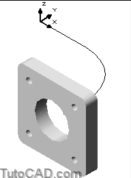
» 2)Open the T301_5.dwg drawing in your personal folder and take a moment to examine the simple 2D objects that have already been created and oriented in 3D space.
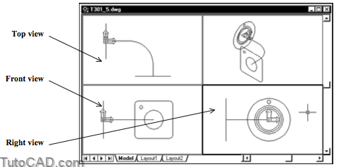
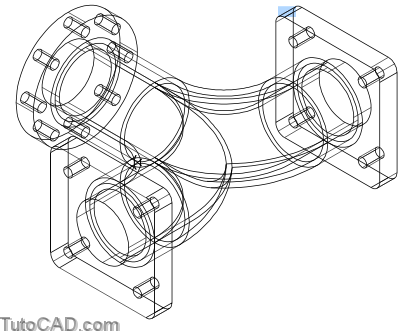
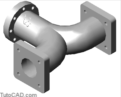
You will use Extrude , Union and Subtract commands to convert these CIRCLEs & LWPOLYLINEs into a SOLID model shown below.
- you will avoid having to change the current UCS (from the default World) by using 3D operations.
»3) Left-click once in the upper right (SE Isometric view) viewport to make it the current viewport.
»4) Pick View + Viewports + 1 Viewport to show only one viewport for the entire screen.
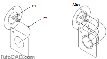
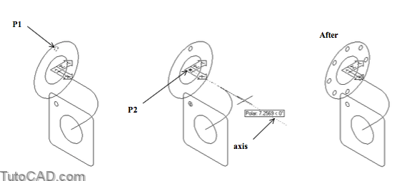
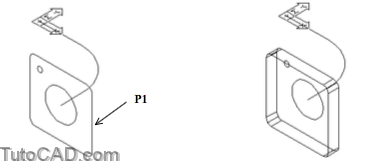
»5) Pick Draw + Solids + Extrude. Select the CIRCLE shown highlighted near P1 and press <enter> to continue. Type P to invoke Path and select the LWPOLYLINE near P2.

You just created a SOLID and the outside of this SOLID will be used to model part of the outside of the pipe fitting.
- the SOLID is red because the current layer (solid) is defined to be red (2D objects are on a white layer called construction).
»6) Make sure POLAR and OSNAP are both On in the status bar. (left-click on them if they are Off).
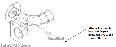
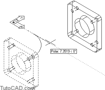
»7) Pick Modify + Mirror and enter L to select the Last object (the SOLID) then press <enter> to continue. Use an Endpoint osnap at the start of the path object near P3 as the first point of the mirror line. Invoke a 0 degree tooltip angle and left-click to use this as the second point of the mirror line. Press <enter> to keep the source objects.
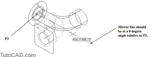
You can use Mirror to create the other side of this pipe fitting
- because the desired mirror plane is perpendicular to the XY plane of the World coordinate system.
- later on you will use Mirror3d because the desired mirror plane will be parallel to the XY plane of the World coordinate system.
» 8) Pick Modify + Solids Editing + Union. Select both new SOLIDs and press <enter> to complete the task.
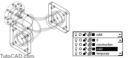
» 9) Select the new SOLID when no other command is running and then select temporary as the layer in the layer drop- down list on the Object Properties toolbar. Pick OK in the alert box that is displayed.
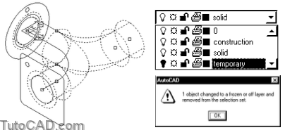
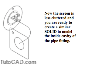
Even in this simple model your screen will quickly become cluttered and it will be difficult to select the desired objects later on.
- you can put SOLIDs on a temporary layer when you do not need those objects for the immediate task
- then leave the temporary layer off until you need to work with the objects that you place on this layer.
10) Pick Draw + Solids + Extrude. Select the CIRCLE shown highlighted near P1 and press <enter> to continue. Type P to invoke Path and select the LWPOLYLINE near P2.
11) Use a similar technique as in step 7 to Mirror this new SOLID about the same axis.
12) Pick Modify + Solids Editing + Union. Select both new SOLIDs and press <enter> to complete the task.
13) Turn the temporary layer On. Pick Modify + Solids Editing + Subtract. Select the large (magenta) outer SOLID near P3 as the objects to subtract from and press <enter>. Select the small (red) inner SOLID near P4 as the objects to subtract and press <enter>.
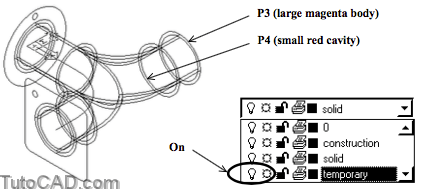
The SOLID you selected to subtract from was on the temporary layer so the new SOLID should be on the temporary layer as well
- even though the current layer is solid.
14) Turn the temporary layer Off again.

15) Pick Modify + 3D Operation + 3D Array. Select the small bolt hole CIRCLE near P1 and press <enter> to continue. Enter P to invoke the Polar option and enter 8 as the number of items. Press <enter> to accept 360 degrees and <enter> to rotate arrayed objects. Invoke an Endpoint osnap at the start of the path near P2 and left-click for the center point of array. Then invoke a 0 degree tooltip angle and left-click to use that point as the second point of the axis. The command line history is shown.
Command: 3DARRAY↵
Initializing… 3DARRAY loaded.
Select objects: (pick small bolt hole CIRCLE near P1)
Select objects: ↵
Enter the type of array [Rectangular/Polar] <R>:P↵
Enter the number of items in the array: 8↵
Specify the angle to fill (+=ccw, -=cw) <360>: ↵
Rotate arrayed objects? [Yes/No] <Y>: ↵
Specify center point of array: (invoke Endpoint osnap near P2 & left-click)
Specify second point on axis of rotation: (invoke 0 degree tooltip angle & left-click)
Command:
16) Pick Draw + Solids + Extrude. Hold your pick box near P1 and left-click to invoke an implied window. Move your crosshairs near P2 to enclose all CIRCLE objects shown highlighted below and left click to select these objects. Then press <enter> to continue. Enter negative 1 as the height and press <enter> to use 0 for the taper angle.
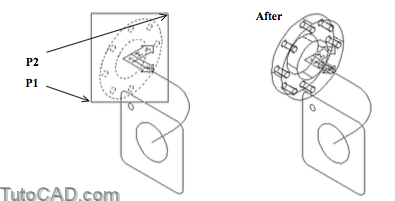
17) Pick Modify + Solids Editing + Subtract. Select the large extruded SOLID near P3 as the object to subtract from and press <enter> to continue. Use an implied window shown below to select all 9 other smaller SOLIDs to subtract
(not the large SOLID) and press <enter> to continue.

18) Pick View + Shade + Gouraud Shaded.
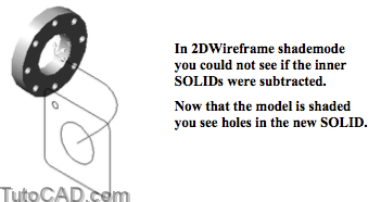
» 19) Pick View + Shade + 2D Wireframe.
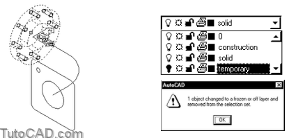
» 20) Select the new SOLID when no other command is running and then select temporary as the layer in the layer drop- down list on the Object Properties toolbar. Pick OK in the alert box that is displayed.
21) Pick Draw + Solids + Extrude. Select the LWPOLYLINE near P1 and press <enter> to continue. Enter positive 1 as the height and press <enter> for a zero angle taper.
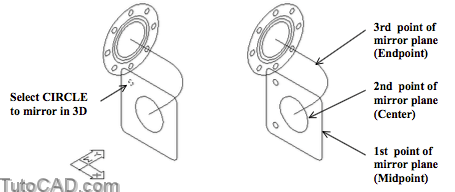
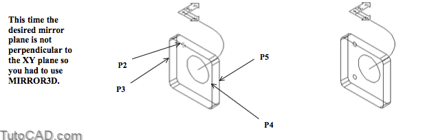
22) Pick Modify + 3D Operation + Mirror 3D. Select the small bolt hole CIRCLE near P2 and press <enter> to continue. Use Midpoint osnaps near P3, P4 & P5 as the three points of the mirror plane. Press <enter> to keep source objects.
23) Use a similar technique to create 2 more bolt holes on the other side of this flange.
24) Pick Draw + Solids + Extrude. Use an implied window to select the 5 CIRCLEs inside the new SOLID and press <enter> to continue. Use a height of 1 and a taper of zero.
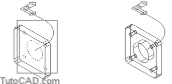
25) Pick Modify + Solids Editing + Subtract. Select the large SOLID as the object to subtract from and press <enter> to continue. Select the 5 circular SOLIDs as the objects to subtract and press <enter>.
26) Pick View + Shade + Gouraud Shaded to verify that you have subtracted the holes in the new SOLID.
27) Pick View + Shade + 2D Wireframe.
» 28) Use a similar technique as in step 7 to Mirror this new SOLID about the same axis.
29) Turn On the temporary layer.
30) Select all SOLIDs on the temporary layer when no command is running then select solid in the layer drop-down list to move these objects to the solid layer. Press <Esc> twice to clear the selected objects.
31) Pick Modify + Solids Editing + Union. Select all 4 SOLIDs to combine them into a single SOLID and press <enter>.
32) Pick View + Shade + Gouraud Shaded to enjoy a shaded view of your finished model.
More practice?
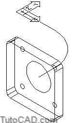
33) Pick Modify + 3D Operation + Rotate 3D. Select the new SOLID and press <enter> to continue. Enter X to rotate the SOLID about the X axis and press <enter> to use the origin as the point on the X axis. Enter 90 as the angle. The command history is shown.
Command: ROTATE3D↵
Current positive angle: ANGDIR=counterclockwise ANGBASE=0
Select objects: (picktheSOLID)
Select objects: ↵
Specify first point on axis or define axis by [Object/Last/View/Xaxis/Yaxis/Zaxis/2points]: X↵
Specify a point on the X axis <0,0,0>: ↵
Specify rotation angle or [Reference]: 90 ↵
Command:
34) Pick View + Zoom + Extents.
35) Pick View + Zoom + Extents.
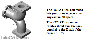
The ROTATE3D command lets you rotate objects about any axis in 3D space.
The ROTATE command rotates about axes that are parallel to the Z axis if the current UCS.
Pick Modify + Copy and enter P to select the Previous object then press <enter> to continue. Enter 10,10 as the displacement then press <enter> at the prompt for the second point of displacement.
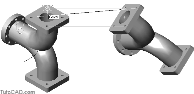
36) Pick Modify + 3D Operation + Rotate3D. Enter L to select the Last copied SOLID and press <enter> to continue. Use Center osnaps on the top of bolt holes near P1 and P2 to specify the start and end (in that order) of the axis for rotation. Enter 45 as the rotation angle.

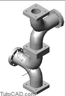
37) Pick Modify + 3D Operation + Align. Enter L to select the Last object again and then press <enter> to continue. Use Center osnaps at the top of the bolt holes shown for the source and destination points. Use the illustration of the aligned components to help you choose appropriate points.
38) Pick View + Zoom + Extents to see all of the aligned assembly on the screen.
39) Pick View + 3D Orbit. Right-click in the drawing area for a shortcut and pick More then Continuos Orbit. Drag slowly in the center of the screen to enjoy seeing your model revolve on-screen. Then press <Esc> to terminate this tool.
40) Save the changes to this drawing & Close the file.
More Practice
Open the T301_6.dwg drawing in your personal folder.
- there are already 4 CIRCLEs created on a construction layer in this drawing.

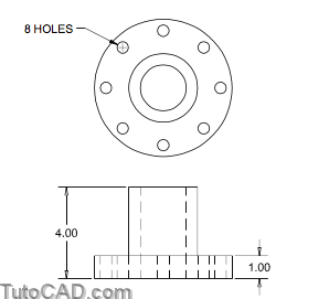
Your task is to use this geometry to create a SOLID model as per the dimensioned sketch below.
- the overall height of the part is 4 units and the flange base has a thickness of 1 unit.
- there are 8 bolt holes equally spaced around the flange and a hole passes through center of the part.