UCSs In Other Orientations
Many 3D models can be created using only orthographic UCSs but there will be times when UCSs in other orientations are required.

- you have already learned how to use the Move, orthoGraphic & World options of the Ucs command in the previous sections.
- in this section you will learn how to use 9 sub-options under New in the Ucs command to create & use UCSs in any orientation.

These Ucs sub-options (under New) can also be invoked directly from the UCS toolbar or a Standard toolbar flyout.
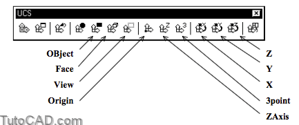
The Origin sub-option of Ucs (under New) is almost the same as the Move option of Ucs, except a new UCS is created instead.

- Origin does not appear in the right-click shortcut above because it is the default option for the New sub option.
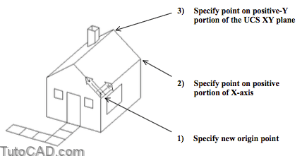
3point is a direct way to define a New UCS in any orientation and it is practical when you can snap to three appropriate points.

- the 1st point becomes the new orign point.
- the 2nd point defines the new direction for the X axis.
- the 3rd point is on the new XY plane on the positive Y side of the X axis (it does not have to be on the new Y axis).
- the positive Z axis direction follows from the right hand rule (see page 3).
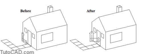
The X, Y and Z options let you rotate the New UCS about the corresponding axis of the current UCS.
- use the other form of the right hand rule to determine the positive direction for rotation about an axis.

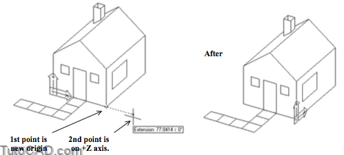
The ZAxis option lets you specify a Z axis vector with two points.

- the 1st point defines the new origin point
- the 2nd point is on the positive portion of the new Z axis.
- you have no control over how the X & Y axes are rotated about this Z axis which limits the usefulness of this option.
The OBject option is similar to the ZAxis option because the orientation of the new Z axis is determined by a selected 2D object.

- the XY plane of the new UCS will be parallel to the XY plane that was in effect when the selected 2D object was created.
The X & Y axes may be rotated differently about the Z axis which limits the usefulness of this option.
- the orientation of the X & Y axes (rotation about Z) depends on which object type you select and where you select the 2D object.
- some 2D object types cannot be selected such as MLINEs, REGIONs, SPLINEs, ELLIPSEs, XLINEs, LEADERs & MTEXT.

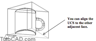
The Face option can be used only on 3D SOLID objects.
- you are prompted to select a face of a 3D SOLID by selecting an edge on the desired face.
One of the adjacent faces of the selected edge is highlighted and a new UCS candidate is displayed (aligned with the selected edge).

- Next will highlight the other adjacent face & the Xflip or Yflip options flip the UCS 180 degrees about the new X or Y axes.
- when you are satisfied with the displayed orientation of the new UCS you can press <Enter> to <Accept> that UCS.

The View option aligns the new UCS XY plane to be perpendicular to the line of sight without changing the current origin point.

- X axis points to the right.
- Y axis points up
- Z axis points directly out of the screen.
PRACTICE CREATING & USING UCSs IN OTHER ORIENTATIONS
» 1) Close the drawing from the previous exercise.
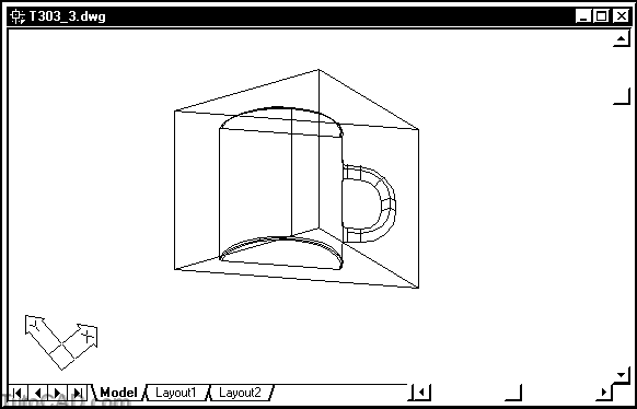
» 2) Open the T303_3.dwg drawing from your personal folder.
» 3) Pick View + Shade + 2D Wireframe.
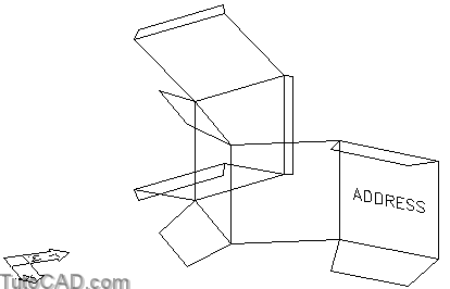
This is a simple surface model for the outer wrapper of a shipping package and you will add TEXT labels on the outside panels.
- these panels are oriented in arbitrary planes so you will have to align UCSs appropriately before using the Dtext command.
- you will want to snap to points that would otherwise be hidden behind surfaces when the Shademode is set to Hidden.
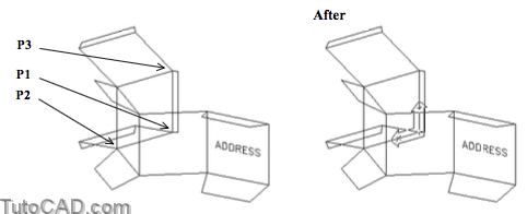
4) Pick Tools + New UCS + 3 Point. Make sure the OSNAP status bar button is On. Use Endpoint (or Intersection) osnaps to pick corners at P1, P2 then P3 (in that order). Then pick View + Display + UCS Icon + Origin to display the new UCS icon at the origin.
5) Make sure the POLAR, OSNAP and OTRACK status bar buttons are On.
6) Right-click on the OSNAP status bar button to invoke a shortcut & select Settings. Then check Midpoint and Insertion as additional running osnaps & pick OK.
7) Pick Draw + Text + Single Line Text. Invoke the Justify option and select Middle. Hold your crosshairs over both Midpoint osnap markers shown (without left clicking) to acquire them as alignment points for tracking. Then invoke the tooltip shown and left-click to use the point in the center of this panel as the insertion point for the TEXT. Press <enter> to accept a height of 0.5 and press <enter> to accept a rotation of 0. Then enter PHOTO#1 as the text string. Press <enter> to terminate Dtext.

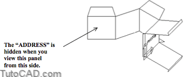
The surfaces in this model will obscure all edges behind them but the new TEXT object will still be completely displayed.
- if you want TEXT objects to be hidden behind surfaces you must assign a small THICKNESS to the TEXT objects.
- you should also move TEXT, that is applied to a surface, a small distance above the surface to avoid round-off errors for Hide.
9) Pick Modify + Move. Follow the dialogue below to move the (last) TEXT object 0.01 above the surface of this panel.
Command: MOVE↵
Select objects: L↵
1 found
Select objects: ↵
Specify base point or displacement: 0,0,.01↵
Specify second point of displacement or <use first point as displacement>: ↵
Command:
10) Pick Modify + Match Properties. Select the text object near P1 as the source then pick the new text object near P2 as the destination object and press <enter> to terminate Matchprop.

11) Pick View + Hide again.

The TEXT object “ADDRESS” already has a small THICKNESS of 0.001 assigned to it
- so when you copied the properties of this object to the new TEXT object it also has a THICKNESS of 0.001.
- you can also use the Properties command to assign a non-zero THICKNESS to selected objects.
Now when you use Hide the TEXT object will be hidden if it is behind surfaces in this model.
» 12) Pick View + 3D Views + NW Isometric.
» 13) Pick View + Hide.
14) Invoke the Previous option of Zoom.
15) Pick Tools + New UCS + Z Axis Vector. Pick near P1 then P2 ( in that order) using either Intersection or Endpoint osnaps for the new origin and point on positive Z axis.

» 16) Pick Tools + New UCS + Y. Then enter negative 90 as the rotation angle about the Y axis.
» 17) Pick Draw + Circle + Center,Diameter. Invoke the Insert osnap shown below and left-click to use it as the center then enter 4 as the diameter.

18) Pick Tools + New UCS + Object and select the TEXT object that you created near P1.

19) Pick Tools + New UCS + Object again but this time select the CIRCLE that you just created near P2.
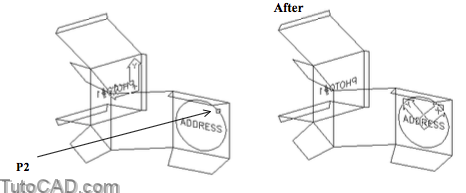
Results will be different for each 2D object type that you select.
- for example, the new X axis is determined by where you select a CIRCLE but it is aligned with selected TEXT instead.
20) Pick Modify + Offset and enter 0.25 as the distance. Select the CIRCLE and pick a point inside as the side to offset. Then press <enter> to terminate the Offset command.

More practice?
21) Thaw the foam insert layer and make it the current layer. Then Freeze the wrapper layer.
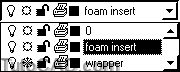
You should use Freeze/Thaw layer settings (instead of On/Off settings) if you plan to use Hide in 3D.
- when objects are on layers that are only turned Off they will still be used to Hide other objects (you must Freeze layers instead).
CIRCLEs (2D) are treated as opaque surfaces when you use Hide
- this can lead to confusing Hide results if there are CIRCLEs on layers which are only turned Off (but are not Frozen).
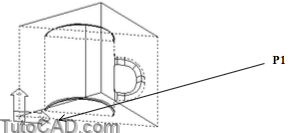
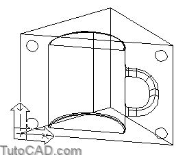
22) Invoke Zoom in realtime mode. Use Pan and Zoom options to display the SOLID model (on the foam insert layer) so that your screen resembles the illustration below.
This drawing file contains a conceptual design for packaging used to ship personalized coffee mugs.
- you were working on the outer wrapper which is a surface model.
- now you will add some alignment pins in the four corners of this SOLID model of a foam insert.
- an assembly will use two of these (identical) foam inserts.
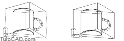
23) Pick Tools + New UCS + Face and select the bottom edge of this foam insert in the lower left corner near P1. Remain in this command (do not do anything else yet).
24) Enter X at the keyboard to invoke the Xflip option. Remain in this command.
25) This time right-click in the drawing area to invoke a shortcut and select Xflip again. Remain in this command.

When you use Xflip the UCS rotates about the X axis (by 180 degrees) and when you use Yflip it rotates about the Y axis instead.
- the Next option is used to highlight the other face (that is adjacent to the same selected edge).
- you can toggle these settings any number of times before pressing <enter> to <accept> the displayed UCS.
» 26) Enter N to use the Next option. Remain in this command
27) Enter N again to return to the previously highlighted face. Then press <enter> to <accept> this orientation.
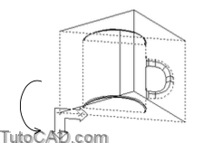
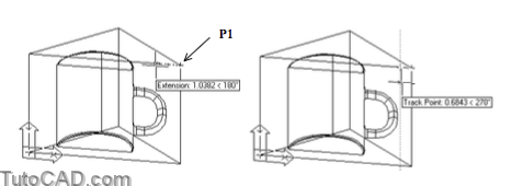
28) Pick Draw + Circle + Center,Diameter. Enter TT and hold your crosshairs over the Endpoint (or Intersection) osnap marker (without left-clicking) near P1 to acquire it as an alignment point for tracking. Move your crosshairs to the left to invoke a 180 degree tooltip angle. Type 0.5 & press <enter> to acquire an alignment point 0.5 from this corner.
29) Move your crosshairs down to invoke a 270 tooltip angle and enter 0.5 to use this point as the circle center. Then enter 0.5 as the diameter.
If you are uncomfortable using tracking you could first place the CIRCLE in the corner then Move it by – 0.5,– 0.5 instead.
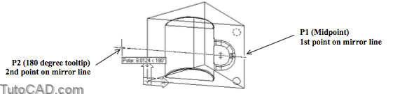
30) Pick Modify + Mirror. Select the CIRCLE and press <enter> to continue. Left-click with a Midpoint osnap to select the first point of the mirror line near P1. Then move your crosshairs to the left to invoke a 180 degree tooltip angle and left-click to use this as the second point of the mirror line. Press <enter> to complete the command.
31) Use a similar technique to Mirror the two CIRCLEs about the middle of this face in the vertical direction.
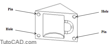
These 2D CIRCLEs are precisely oriented on this face and are ready for the Extrude command.
- you could Extrude two CIRCLEs by negative 0.125 with a 10 degree taper & Subtract them from the SOLID to make holes
- then Extrude the other two CIRCLEs by positive 0.125 with a 10 degree taper & Union them with the SOLID model to make pins.
32) Save the changes to this drawing and Close the file.