Getting Started In 3D
You are normally not concerned with the Z axis and Z ordinates are usually zero when you use AutoCAD for 2D drafting & design
- but you can specify Z ordinates other than zero (when AutoCAD prompts for points) to create objects in 3 dimensions.

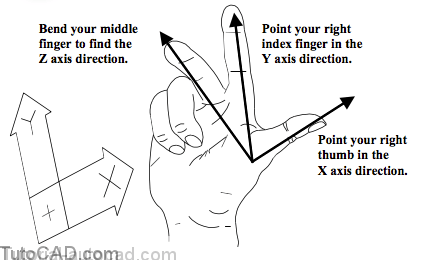
Right Hand Rule And The UCS
You can define your own customized axes for X,Y & Z at any orientation using a variety of different tools
- and you can use familiar 2D commands in 3D if you understand how to change the current User Coordinate System (UCS).
- tools to manage the UCS are covered in detail in the User Coordinate Systems In 3D (T303) document.
Viewing Tools
You can change your point of view in a variety of different ways and you can change the way 3D models appear in plots or on-screen.
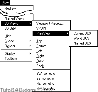
Many tools for viewing 3D models can be invoked from the Viewpulldown menu & you will use some of these tools in this document.
- Viewing tools are covered in more detail in the Viewing 3DDrawings (T302) document.
- rendering tools are also introduced in the Introduction ToRendering (T306) document.
2D Geometry For 3D Models
You probably know more about 3D modeling than you realize if you already know how to create 2D geometry in AutoCAD.
- you can draw familiar 2D objects on any plane in 3D once you have learned how to change the current UCS.
- 2D models (floor plans for “walk through”) may even be quickly converted to 3D models without having to change the UCS.
REGIONs and LWPOLYLINEs are practical 2D objects commonly used to generate (other) 3D objects.
- use Pline to create LWPOLYLINEs directly or use Pedit to convert selected ARCs & LINEs into LWPOLYLINEs.
- use the Region command to convert closed LWPOLYLINEs and CIRCLEs into REGION objects.
- you can combine REGIONs using Union, Subtract & Intersect commands which makes this 2D object very powerful in 3D.
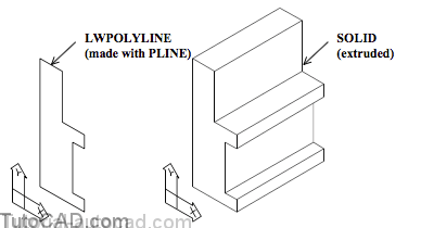
For example, you could use the Pline command directly to draw the outline profile shown below
- and this 2D LWPOLYLINE could be converted into a 3D SOLID (by using the Extrude command which is covered later on)
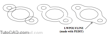
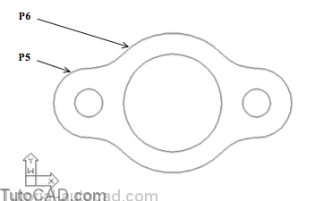
You could use Circle and then Trim & Fillet to create 2D geometry for the gasket shown below (made up of ARCs & CIRCLEs)
- then use the Join option of Pedit to convert the ARC segments around the outer profile into a single LWPOLYLINE object.
The inner CIRCLEs & outer LWPOLYLINE could then be converted into individual REGION objects using the Region command
- and you could Subtract the (circular) REGIONs from the (outer) REGION to create one new 2D REGION (with holes in it).
- the new REGION could be easily converted into a 3D SOLID (by using the Extrude command which is covered later on).

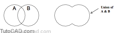
You can use standard boolean operations to combine several REGIONs (in the same plane) into a single REGION.
- these boolean operations can be used on REGIONs (in 2D) and also on SOLIDs (in 3D).
Use Union to create a new REGION that includes the combined areas of the selected REGIONs.
- you are prompted to select REGIONs (or SOLIDs) to join together and you can pick as many objects as you wish.
Use Subtract to remove the areas of selected REGIONs from another larger REGION.
- this is a two part command in which you are first prompted to select REGIONs (or SOLIDs) that you will subtract from.
- then you are prompted to select the REGIONs (or SOLIDs) that you would like to subtract.

Use Intersect to generate a new REGION that includes only the areas that all of the other selected REGIONs have in common.

PRACTICE CREATING 2D GEOMETRY FOR 3D MODELS
»1) Launch AutoCAD (if required). Pick File + Open and select the T301_1.dwg drawing file in your personal folder. Close all other drawings (if other drawings are open).
»2) Pick Tools + Run Script. Select the T301.scr script file in your personal folder and pick the Open button there to run this script. This sets several system variables to match the behavior illustrated in this manual.
»3) Pick Modify + Trim and press <enter> when prompted for cutting edges (to use ALL objects as cutting edges). Then pick the CIRCLEs near P1, P2, P3 & P4 as objects to trim. Press <enter> to terminate Trim.

»4) Pick Modify + Fillet and invoke the Radius option. Enter 1.5 as the new radius.
»5) Right-click in the drawing area to invoke a shortcut and select Repeat Fillet. Pick the two ARCs near P5 & P6. Use a similar technique to complete the outline as shown.
6) Pick Modify + Polyline. Select any outer ARC and press <enter> to respond Yes when asked if you want to turn it to a polyline. Enter J to invoke the Join option and enter ALL to select all objects in the drawing. Press <enter> to continue and press <enter> again to complete the command. The command line history is shown.
Command: PEDIT↵
Select polyline: (pick any outer ARC)
Object selected is not a polyline
Do you want to turn it into one? <Y> Y↵
Enter an option [Close/Join/Width/Edit vertex/Fit/Spline/Decurve/Ltype gen/Undo]: J↵
Select objects: ALL↵
11 found
Select objects: ↵
7 segments added to polyline
Enter an option [Open/Join/Width/Edit vertex/Fit/Spline/Decurve/Ltype gen/Undo]: ↵
Command:
» 7) Pick Draw + Region. Enter ALL to select the LWPOLYLINE and 3 CIRCLEs and press <enter> to complete this command.
» 8) Pick Modify + Solids Editing + Subtract. Follow the command line history below to subtract the three circular REGIONs from the outer REGION.
Command: SUBTRACT↵
Select solids and regions to subtract from .. Select objects: (pick outer REGION near P1)
Select objects: ↵
Select solids and regions to subtract ..
Select objects: (pick circular REGION near P2)
Select objects: (pick circular REGION near P3)
Select objects: (pick circular REGION near P4)
Select objects: ↵
Command:

When you first opened the drawing there were 6 (ordinary) CIRCLEs created in the (default) World Coordinate System.
- you used Trim to change some of these CIRCLEs to blended ARCs (each ARC ends precisely where the next ARC begins).
- you used Pedit to turn the outer ARCs into one LWPOLYLINE.
- you used Region to convert the LWPOLYLINE & 3 remaining CIRCLEs to REGION objects.
- you used Subtract to remove the area of the circular REGIONs from the outer REGION.
9) Pick View + 3D Views + SE Isometric to view the model from a 3D viewpoint.

When you look at the UCS icon in the lower left corner of the screen you see the X and Y axes in a different orientation.
- the positive Z axis is pointing in the direction (up) that the positive Y axis normally points in when you create 2D drawings.
10) Point your right hand thumb in the direction indicated by the X axis in the UCS icon. Point your right hand index finger in the Y axis direction and bend your middle finger to indicate the direction of positive Z.

11) Pick Draw + Solids + Extrude. Select the REGION and press <enter> to continue. Enter 0.2 as the height and press <enter> to use 0 as the taper angle. The 2D REGION is now converted to a 3D SOLID that is 0.2 units thick.

12) Pick View + Shade + Flat Shaded.

13) Pick View + 3D Orbit. Right-click in the drawing area to invoke a shortcut. Pick More then pick Continuous Orbit. Pick a point near the center of the screen and drag your cursor slowly in any direction. When you release your mouse button the 3D SOLID will revolve continuously on-screen.

You can drag again (while the model is spinning) to change the way the model appears to be spinning on-screen.
You can right-click in the drawing area while using the Continuous Orbit tool to invoke the same shortcut
- then select the Zoom option (like Zoom in realtime) to make the model appear smaller on-screen
- then right-click to invoke the shortcut & select Continuous Orbit again to spin the model in real time.
» 14) Press <Esc> to terminate the Continuous Orbit tool.
» 15) Pick View + Shade + 2D Wireframe.
» 16) Pick View + 3D Views + Top

The model was never really revolving in 3D space (you were the one moving to view the model from different viewpoints).
- 3dorbit is a powerful but intuitive tool & you can learn how to use more features in the Viewing 3D Drawings (T302) document.
- you can also learn more about shademodes in that document.
With minimal effort you were able to create a simple 3D model from familiar 2D objects and you did not even have to change your UCS.
- when you learn how to change the current UCS you can create 2D objects in any orientation for more complicated models.
- you can learn more about changing the UCS in the User Coordinate Systems (T303) document.
» 17) Save your changes to this drawing and Close the file.