Viewports For 3D Models
It is practical to view 3D models from more than one viewpoint It is practical to view 3D models from more than one viewpoint
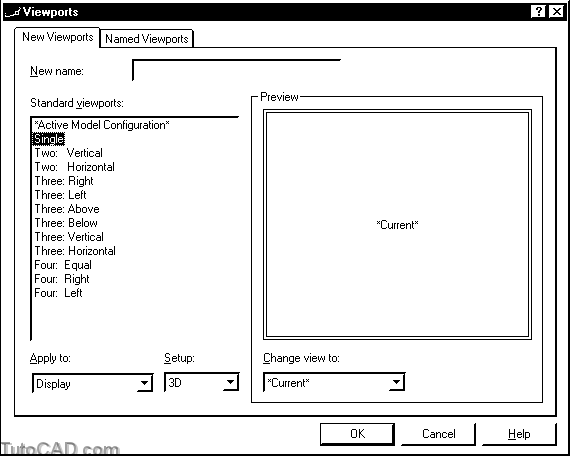
- you can use the Vports command to create and manage multiple viewports and there are standard viewports available for 3D.
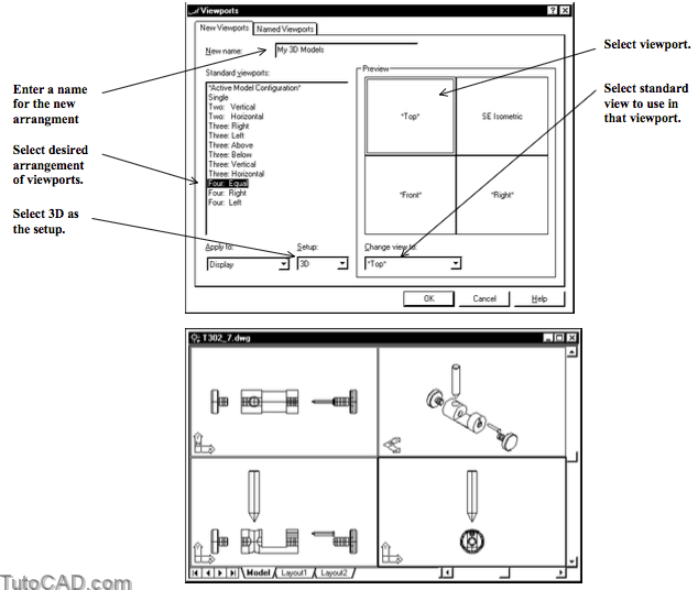
It is easy to customize an arrangement of viewports to use different standard viewing directions.
- click in the desired viewport pane in the preview area then select the desired view for that viewport in the drop-down list.
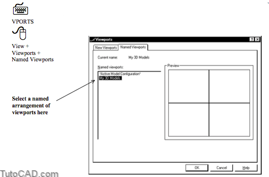
If you give your viewport arrangements a name you can restore them at any time using the Named Viewports tab of Vports.
- select the desired viewport arrangement to restore & pick OK.
You can also use Vports to display a single viewport again.
- make the desired viewport the active viewport BEFORE invoking the Vports command.
- select Single in the standard viewports list and pick OK.
- this is the same as picking View + Viewports + 1 Viewport on the pulldown menu.
Hide Plot
When you create viewports on a Layout you may want one or more of the viewports on that layout to Plot with hidden lines removed.
- this is achieved by turning Hide Plot On for the desired viewport.
- viewport(s) (on Layouts) with Hide Plot set to Yes automaticallyPlot with hidden lines removed each time you Plot.
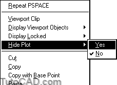
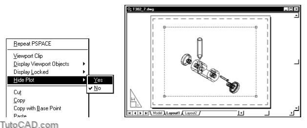
- You can toggle Hide Plot On or Off by selecting the desired viewport on a Layout when no command is running
- right-click in the drawing area to invoke a shortcut.
- then select Hide Plot and pick either Yes or No to change the current setting for the selected viewport.
You can also change the Hide Plot setting using the Properties command (in the Misc category).
You can automatically create appropriate viewports on Layouts to Plot 2D drawings of 3D SOLID models.
- this feature is explained in the T305 document called Generating 2D Drawings From Solid Models.
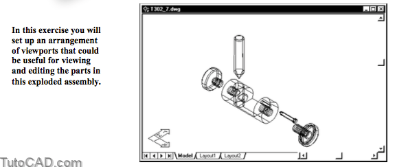
PRACTICE CREATING & MANAGING MULTIPLE VIEWPORTS FOR 3D
» 1) Close the drawing from the previous exercise if it is open.
» 2) Open the T302_7.dwg drawing in your personal folder.
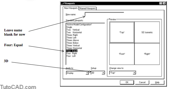
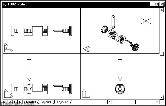
3) Pick View + Viewports + New Viewports. Select 3D as the Setup. Pick Four: Equal standard viewports. Then pick OK without entering a name for this arrangement.
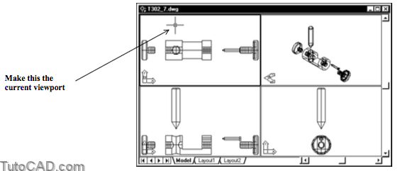
Initial views in the new viewports will be zoomed in to the drawing extents which does not leave any margin space in each view.
- you will adjust the views in each viewport (to add a margin) then use Vports again to name this viewport arrangement.
4) Left-click once in the upper left (Top) view to make this the current viewport.
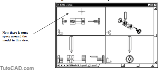
5) Pick View + Zoom + Scale and enter 0.8X to reduce the magnification of this view by 20%.
6) Repeat for the other two orthographic views.
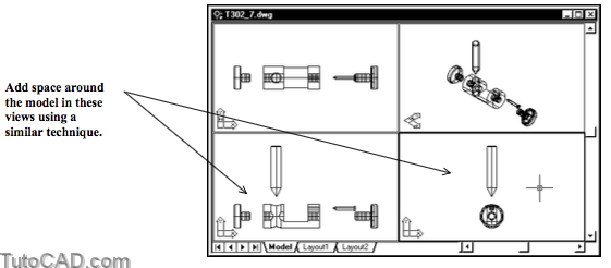
Display commands affect ONLY the current viewport.
- left-click once in a different viewport to make it current.
- you can change the current viewport while a command is running (provided it is not a display command).
7) Pick View + Viewports + New Viewports again. Type My 3D Models as the New name. Active Model Configuration should be the selected Standard viewports. Then pick OK.
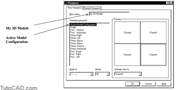
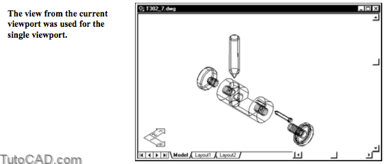
8) Left-click once in the upper right (SE Isometric) view to make this the current viewport.
9) Pick View + Viewports + 1 Viewport.
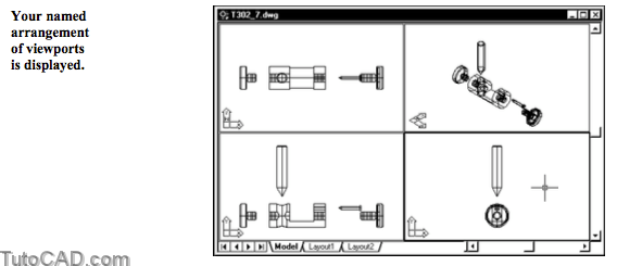
10) Pick View + Viewports + Named Viewports. Select My 3D Models from the list of Named viewports and pick OK.

More practice?
» 11) Make Viewport the current Layer.
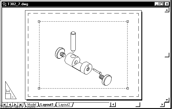
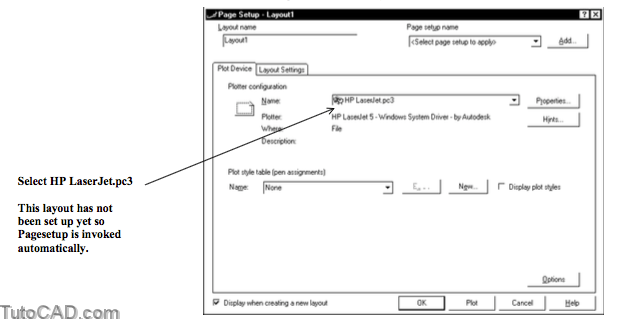
» 12) Left-click on the Layout1 tab to invoke the Page Setup for this layout. Select the HP LaserJet.pc3 file (or equivalent) Plotter configuration then pick OK.
13) Left-click on PAPER in the status bar to switch to MODEL.
14) Pick View + 3D Views + SE Isometric.
15) Left-click on MODEL in the status bar to switch to PAPER.
16) Select the viewport to make it highlighted and right-click in the drawing area to invoke a shortcut. Pick Hide Plot then select Yes for the selected viewport.
17) Pick File + Plot Preview to see what a Plot would look like. Then press <enter> to complete the preview.
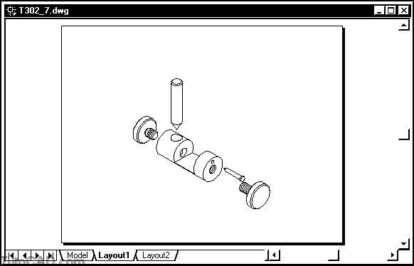
- This viewport will appear with hidden lines removed whenever you Plot this layout (unless you explicitly change Hide Plot again).
- The DISPSILH system variable is already set to 1 in this drawing so the curved surfaces are displayed with the mesh suppressed.
18) Save the changes to this drawing then Close the file.
More Practice
Open the Campus drawing file which is supplied with AutoCAD software (by Autodesk) with other Sample drawings.
- your instructor may have already copied this file to yourpersonal folder.
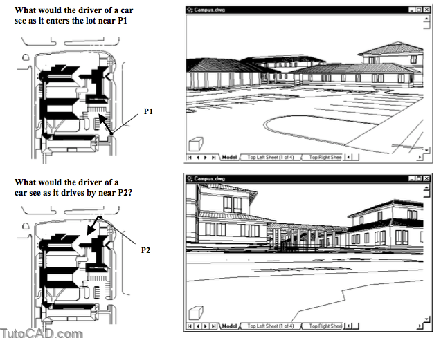
Set up camera & target points to simulate a helicopter hovering above the perimeter of the campus looking toward the site center.
- with Shademode set for Hidden simulate what the pilot would see using a continuous orbit about the campus.
- assume the helicopter is 150 feet above the campus.