UCSs In Multiple Viewports in a 3D drawing
Before all viewports always used the current UCS.
- now each viewport can be associated with a unique UCS if you choose to Save UCS with viewport (default in AutoCAD 2000).
- you automatically use the UCS saved with a viewport when you make that viewport the current viewport.
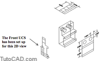
For example, this new feature makes it easier to dimension 2D drawings that have been projected from a 3D SOLID.

This technique for automatically creating 2D drawings from 3D SOLIDs is beyond the scope of this document.
- see the Generating 2D Drawings From Solid Models (T305) document for more information.
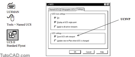
You can change the UCSVP setting for the current viewport on the Settings tab of the Ucsman dialogue box.
- Save UCS with viewport is checked by default (UCSVP = 1).
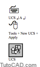
The Apply option of Ucs can be used to quickly change the UCS that is saved in all active viewports.
- for example, you might want to apply the World UCS to all active viewports on a Layout.
- this option lets you perform this in one operation (compared to restoring the World UCS one-at-a-time in each viewport).
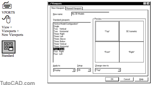
When you use the Vports command to set up viewports for 3D, the UCS in each viewport will be an appropriate orthographic UCS
- provided the UCSORHTO system variable has not been changed from the initial setting.
PRACTICE USING UCSs WITH MULTIPLE VIEWPORTS
»1) Close the drawing from the previous exercise if it is open.
»2) Open the T303_5.dwg drawing from your personal folder.

»3) Pick View + Display + UCS Icon + Origin to display the UCS icon at the origin of the current UCS.
»4) Pick Tools + Orthographic UCS + Front.
5) Pick Tools + Orthographic UCS + Right.

6) Pick Tools + Orthographic UCS + Top.

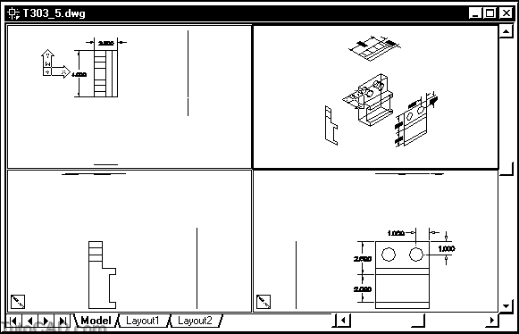
7) Pick View + Viewports + New Viewports. Select 3D as the Setup. Pick Four: Equal standard viewports. Then pick OK without entering a name for this arrangement.
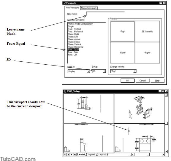
8) Pick Tools + Named UCS. Select the Orthographic UCSs tab and verify that Right is already the current UCS in the lower right viewport. Then pick Cancel.
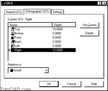
Each viewport uses an appropriate UCS and these UCSs are saved with each viewport.
- you can change the current viewport and the current UCS is automatically changed to the UCS saved to that viewport.
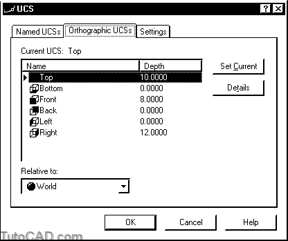
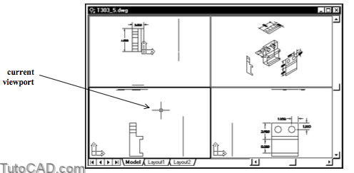
» 9) Left-click in the upper left (top) viewport to make it current.
» 10) Pick Tools + Named UCS. Select the Orthographic UCSs tab and verify that Top is already the current UCS in the upper left viewport. Then pick Cancel.
11) Left-click in the lower left viewport to make it current.
12) Pick Tools + New UCS + Apply. Left-click once in the upper right viewport then press <enter>.
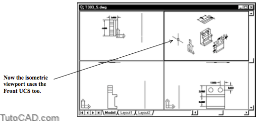
13) Pick Tools + New UCS + World. Pick Tools + New UCS + Apply & enter A to apply the WCS to All viewports.
You can Apply the current UCS to one other viewport or you can Apply the current UCS to all viewports.
- you can use this technique on the Model tab as well as on Layout tabs (when MODEL appears in the status bar).
More practice?
» 14) Select the Layout1 tab
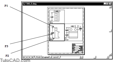
» 15) Double-click in the Front viewport to switch to the MODELand make this the current viewport.

This layout has already been set up to display only appropriate layers in each viewport.
- you could Plot the layout to create a 2D drawing of this model.
» 16) Pick Dimension + Linear. Use Endpoint osnaps near P1 and P2 as the extension line origin points then pick near P3 (no osnap) as the dimension line location to create a dimension in the front viewport.
» 17) Left-click once in the Top viewport to make it current.
» 18) Make Top-DIM the current Layer.

19) Pick Dimension + Linear. Use Endpoint osnaps near P1 and P2 as the extension line origin points then pick near P3 (no osnap) as the dimension line location to create a dimension in the top viewport.
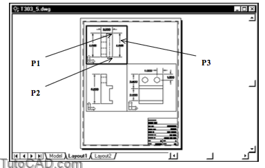
You did not have to change the UCS to create a dimension in this plane because the Top UCS is already assigned to this viewport
- the dimension layers are already set up to be visible only in the viewports that they are intended to be created in.
- Front-DIM, Top-DIM & Right-DIM layers are for dimensions in the corresponding viewports.
Still more practice?
» 20) Create more dimensions on appropriate layers in these three viewports for extra practice.
» 21) Save the changes to this drawing and Close the file.
More Practice
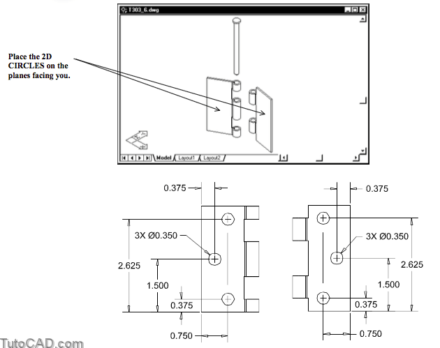
Open the T303_6.dwg file in your personal folder.
- this file contains solid models for the left and right sides to a common door hinge.
The models are incomplete because there are no mounting holes.
- in this exercise you will sketch the mounting holes as 2D CIRCLEs in the appropriate planes.
- the hinge plates are oriented arbitrarily in the 3D space so you must define appropriate UCSs to create the CIRCLEs.
- draw these CIRCLEs on the sides of the hinge plates that are facing you in the current view.
Still more practice?
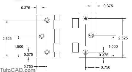
Mounting holes for hinges are typically intended for flat head screws so the holes should actually be tapered (counter-sunk).
- a section view through one of the holes is shown below to illustrate both diameters of this tapered hole.

- Sketch 6 more CIRCLEs on the back planes of these hinge plates this time, using a diameter of 0.225
You could use Offset to create smaller diameter CIRCLEs then use Move to move the smaller CIRCLEs to the correct planes.
If you were to model these holes using SOLIDS you could have created the smaller diameter CIRCLEs first
- and Extrude these CIRCLEs by the thickness of the plate and Subtract them from the plate to make cylindrical holes.
- then a 45 degree Chamfer with a distance equal to the plate thickness could be applied to the outer edge of each hole.