How to use User & World Coordinate Systems UCS WCS
Here is how to use CS WCS (User & World Coordinate Systems) in AutoCAD
The World Coordinate System (WCS) is the default coordinate system used by AutoCAD.
- the WCS will be sufficient for most of your 2D drafting needs and this is the only coordinate system used in this course.
- you know that the current coordinate system is the WCS when you see the letter W in the UCS icon.

If you plan to work with 3D drawings or with drawings that are oriented at an odd angle (e.g. site plans not square to the world)
- then you may want to learn how to create and manage your own User Coordinate System (UCS).
- you know the current coordinate system is a UCS when there is no W in the UCS icon.
To learn more about creating and managing your own UCS use the AutoCAD Help utility
- search for help on UCS Command (ACR – AutoCAD Command Reference)
PRACTICE : Using UCS command in AutoCAD tutorial
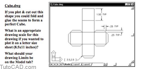
Create a drawing from scratch using English default settings and save this new drawing as Cube.dwg in your personal folder.
- use a method of your choice to create the LINEs shown in the illustration below.
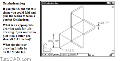
Create a drawing from scratch using English default settings and save this drawing as Octahedron.dwg in your personal folder.
- use a method of your choice to create the LINEs shown in the illustration below.
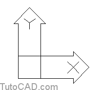
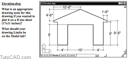
Create a new drawing from scratch using English default settings and save this drawing as Elevation.dwg in your personal folder.
- use a method of your choice to create the LINEs shown in the illustration below.
This drawing will be easier to complete if you use the Units command & select Architectural as the type of units for length.
- then you could enter distances using feet and inches.
- for example, with Architectural units you could type 10’6 for 10 feet + 6 inches = 126 inches (one drawing unit equals one inch).
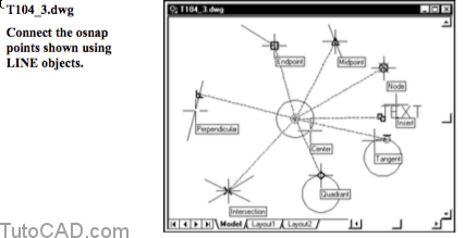
Open a drawing called T104_3.dwg in your personal folder.
- use the Line command to connect the osnap points from the center of the inner CIRCLE to the osnap points shown.
- the appropriate osnap mode to use is indicated for each LINE as well as where to hold your crosshairs for these osnap points.