Creating MLINEs
The Mline command creates MLINE objects that can have multiple elements and multiple segments in the same MLINE object.
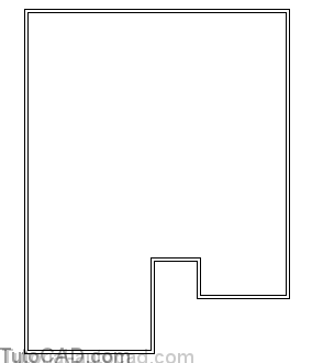
- for example, the outer walls of a house plan shown below could be modeled using a single MLINE object.
- in this example, there are 2 elements (one for each side of the wall) and 8 segments (one for each wall section).
When you invoke the Mline command AutoCAD reports the current settings on the command line & you are prompted for the start point.
- you can create MLINE segments like you would using the Line command once you are satisfied with the current settings.
Command: MLINE ↵
Current settings: Justification = Top, Scale = 1.00, Style = STANDARD Specify start point or [Justification/Scale/STyle]: (pick point or use an option)
Next point: (etc.)
You can change settings at the first Mline prompt and these settings are retained in the drawing for the next Mline command.
- you can create and use many different MLINE styles in a drawing and the current MLINE style is used by default.
- scale is used to control overall width of all MLINE segments (e.g. the wall thickness if you use MLINEs to make walls)
- justification controls which MLINE element is aligned with your points (e.g. are the points for the inside or outside of a shape?).
Your choices for justification are Top, Zero and Bottom and these terms can be misleading.
- the top element is at the top only when you create an MLINE segment from left to right in a horizontal direction.
Command: MLINE ↵
Current settings: Justification = Top, Scale = 1.00, Style = STANDARD Specify start point or [Justification/Scale/STyle]: J ↵
Enter justification type [Top/Zero/Bottom] <top>: (select a different justification)
You should consider which side (or the middle) of the MLINE you are prepared to supply the endpoints for before you invoke Mline.
- the illustration below shows the same MLINE segment created between points 1 & 2 (in that order) for each justification option.
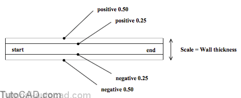
- this MLINE example has three elements with offset values of +0.5, +0.25 and –0.5.

When you define an MLINE style you can add several elements and specify the offset amount for each element.
When you define offsets it helps to imagine that you are standing at an MLINE vertex & looking at the next vertex along the MLINE.
- positive offsets will be on your left side (the Top).
- negative offsets will be on your right side (the Bottom).

Each drawing created from scratch has the STANDARD style already defined as the current MLINE style.
- the STANDARD style creates double lines with offsets at +0.5 and –0.5 so the overall MLINE width is 1.0 x the Scale factor.
- use Mlstyle to define new styles or select other styles (that have already been defined) to be the current style.
- once you have created MLINEs with a specific style in a drawing you will not be able to change the properties for that style.

Pick the Element Properties button to change elements.
- use Add/Delete to change the number of elements (to a maximum of 16 elements).
- enter Offsets for each selected element in the offset edit box.
- specify Color & Linetype for the selected element.
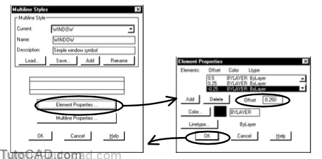
For example, you could have the following offsets to model a window symbol with an MLINE object that has 4 elements.
- then set the scale to the overall wall thickness before you draw the window inside a wall in plan view.
Pick the Multiline Properties button to control
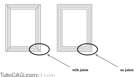
- the display of joints
- or select capping options
- or set fill options.

Caps can be LINEs, ARCs both or none.
- check the desired box for the start and end of the MLINE object.
- angles can be changed from the default of 90 degrees.
- for odd numbers of elements a middle line remains uncapped.
If the Fill box is checked a background color can be selected.
If Display joints is checked the joints are displayed as shown below.
PRACTICE CREATING SIMPLE MLINES
» 1) Close the drawing from the previous exercise if it is open.
» 2) Open the T208_7.dwg drawing in your personal folder.
» 3) Verify that POLAR is On in the status bar.
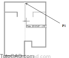
» 4) Pick Draw + Multiline. Enter S to invoke Scale then enter 6 as the new scale for a 6 inch wall. Follow the dialogue below to create the outer walls for the house plan shown. Use the POLAR tool to invoke the tooltip angles shown. This drawing uses Architectural units in inches so you must remember to add the apostrophe after distances & ordinates for feet.
Command: MLINE ↵
Current settings: Justification = Top, Scale = 1.00, Style = STANDARD Specify start point or [Justification/Scale/STyle]: S ↵
Enter mline scale <1.00>: 6 ↵
Current settings: Specify Justification = Top, Scale = 6.00, Style = STANDARD
Specify start point or [Justification/Scale/STyle]: 23′,7′ ↵
Specify next point: 56′ (90 POLAR tooltip angle) ↵
Specify next point or [Undo]: 43′ (0 POLAR tooltip angle) ↵
Specify next point or [Close/Undo]: 47′ (270 POLAR tooltip angle) ↵
Specify next point or [Close/Undo]: 15′ (180 POLAR tooltip angle) ↵
Specify next point or [Close/Undo]: 6′ (90 POLAR tooltip angle) ↵
Specify next point or [Close/Undo]: 7′ (180 POLAR tooltip angle) ↵
Specify next point or [Close/Undo]: 15′ (270 POLAR tooltip angle) ↵
Specify next point or [Close/Undo]: C↵
Command:
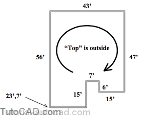
You are using the default Top justification and you are creating these walls in a clockwise direction
- so the dimensions you entered for these walls correspond to the outside edges of these walls.
5) Pick Format + Multiline Style. Enter INTERIOR_WALLS as the (new) Name & enter Standard with end caps as the description. Pick Add but remain in this dialogue box.

5) Pick the Multiline Properties button then Check the Start & End for Line caps. Pick OK to return to the Multiline Styles box and pick OK again to complete the command.

Now there are two multiline styles defined in this drawing.
- initially you had the default STANDARD style that is defined in new drawings created from scratch
- you added a new style called INTERIOR_WALLS based on STANDARD but with caps added to the start & end of lines.
- the current style is INTERIOR_WALLS so this style will be used the next time you create multilines.
- the preview in the Multiline Styles box shows the end caps for this new style.
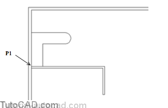
7) Zoom In to the window shown below.
8) OTRACK & OSNAP should both be On in the status bar.
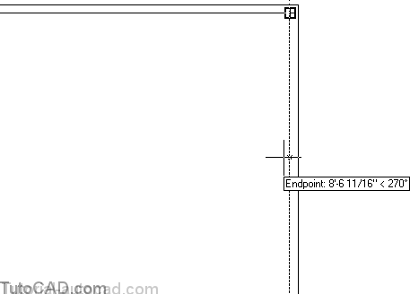
9) Pick Draw + Multiline. Enter S to invoke Scale and enter 4 for 4 inch interior walls. Enter J to invoke Justification and enter B to use Bottom. Hold your crosshairs over the Endpoint marker shown near P1 below (do NOT left-click) to acquire this as a tracking alignment point.
Command: MLINE ↵
Current settings: Justification = Top, Scale = 6.00, Style = INTERIOR_WALLS Specify start point or [Justification/Scale/STyle]: S ↵
Enter mline scale <6.00>: 4 ↵
Current settings: Justification = Top, Scale = 4.00, Style = INTERIOR_WALLS Specify start point or [Justification/Scale/STyle]: J ↵
Enter justification type [Top/Zero/Bottom] <top>: B ↵
Current settings: Justification = Bottom, Scale = 4.00, Style = INTERIOR_WALLS Specify start point or [Justification/Scale/STyle]: (acquire P1 as a tracking point)

You will use tracking to start a new horizontal wall 10 feet below P1 in the next step.
10) Move your crosshairs down to invoke a 270 tooltip angle and enter 10’ as the distance to the start point.
Specify start point or [Justification/Scale/STyle]: 10′ (270 tooltip angle) ↵
11) Use the following command line history to complete the new wall that is 13 feet horizontally with a 5 foot vertical section.
Specify next point: 13′ (180 tooltip angle) ↵
Specify next point or [Undo]: 5′ (270 tooltip angle) ↵
Specify next point or [Close/Undo]: ↵
Command:

Even though you used the Bottom justification it may seem as though you used Top because you went from right to left.
- the dimensions for these two walls correspond to “bottom” side of this MLINE as shown in the illustration above.
The intersection of this MLINE with the MLINE for the outer walls requires some cleaning up
- you will learn how to do this in the Editing MLINEs section.
12) Zoom back out to the Previous view.
13)Pick Modify + Mirror. Enter L to select the Last MLINE object and press <enter> to continue. Use a Midpoint osnap near P1 for the start of the mirror line then move your crosshairs down to invoke a 270 tooltip angle and left-click to use that point as the other end of the mirror line. Press <enter> to keep the original MLINE.
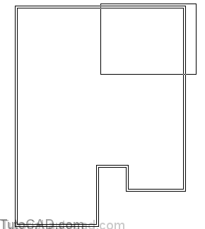
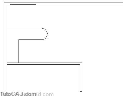
14) Pick Format + Multiline Style. Enter COUNTER as the new Name and enter Counter top with one round end as the Description. Pick the Add button. Pick the Multiline Properties button and uncheck the End Cap for Line and check the End Cap for Outer arc. Pick OK to return to the Multiline Styles box & pick OK to complete the command.

You just created a new style called COUNTER that you can use to create counter tops with one round end segment (see preview).
- this is also the current multiline style.
15) Zoom In to the window shown below.

16) Make Counters the current layer.
17) Pick Draw + Multiline. Enter S to invoke Scale and enter 24 for a 24 inch counter. Enter J to invoke Justification and enter T to use Top. Use an Endpoint osnap near P1 as the start point. Invoke a 90 tooltip angle and enter 6’ as the distance for the first segment. Invoke a 0 tooltip angle and enter 6’ for the distance of the second segment. Press <enter> to complete the MLINE.
Command: MLINE ↵
Current settings: Justification = Bottom, Scale = 4.00, Style = COUNTER Specify start point or [Justification/Scale/STyle]: S ↵
Enter mline scale <4.00>: 24 ↵
Current settings: Justification = Bottom, Scale = 24.00, Style = COUNTER Specify start point or [Justification/Scale/STyle]: J ↵
Enter justification type [Top/Zero/Bottom] <bottom>: T ↵
Current settings: Justification = Top, Scale = 24.00, Style = COUNTER Specify start point or [Justification/Scale/STyle]: (Endpoint near P1) Specify next point: 6′ (90 tooltip angle) ↵
Specify next point or [Undo]: 6′ (0 tooltip angle) ↵
Specify next point or [Close/Undo]: ↵
Command:
18) Pick Format + Multiline Style. Enter WINDOW as the new Name and enter Simple window symbol as a description. Pick the Add button. Pick the Multiline Properties button and check End Caps for Line and uncheck End Caps for Outer arcs. Then pick OK to return but do NOT close the Multiline Styles box yet.

19) Pick the Element Properties button. Pick Add in the Element Properties box and type 0.25 as the Offset then press the <enter> key. Pick Add again and enter negative 0.25 as the Offset and press <enter> again. Pick OK to return to the Multiline Styles box and pick OK to complete the Mstyle command.

You just created a new style that you could use to create simple window symbols with.
- this is the current style and you will use it to create a window in the next step.
» 20) Make Windows the current layer.
» 21) Pick Draw + Multiline. Enter S to invoke Scale and enter 6 for a 6 inch wide window (to match width of outer walls). Enter J for Justification and enter B for Bottom. Hold your crosshairs over the Endpoint osnap near P1 (do NOT left- click) to acquire this as a tracking alignment point.
Command: MLINE ↵
Current settings: Justification = Top, Scale = 24.00, Style = WINDOW Specify start point or [Justification/Scale/STyle]: S ↵
Enter mline scale <24.00>: 6 ↵
Current settings: Justification = Top, Scale = 6.00, Style = WINDOW Specify start point or [Justification/Scale/STyle]: J ↵
Enter justification type [Top/Zero/Bottom] <top>: B ↵
Current settings: Justification = Bottom, Scale = 6.00, Style = WINDOW

22) Move your crosshairs to the right to invoke a 0 tooltip angle and enter 6 (inches) as the distance. Then enter 4’6 (4 feet 6 inches) as the distance with the same 0 tooltip angle and press <enter> to complete Mline.
Specify start point or [Justification/Scale/STyle]: 6 (0 tooltip angle) ↵Specify next point: 4’6 (0 tooltip angle) ↵
Specify next point or [Undo]: ↵
Command:
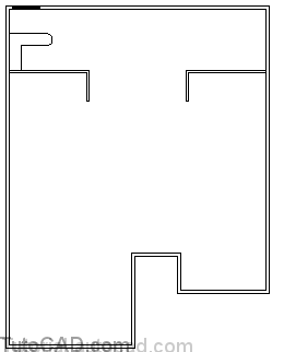
23) Zoom back out to the previous view.
24) Save the changes to your drawing for the next exercise.
This simple drawing contains only 5 objects and they are all MLINEs.
- with relatively little effort you have defined new MLINE styles that could be used to create a relatively complex house plan.
- in the next section you will learn how to edit MLINEs so you can work more effectively with these advanced object types.