How to use Dimensions For Distance
Free course how to use Dimensions For Distance in AutoCAD
Dimension origins are created as definition points (defpoints for short) on a special Layer called DefPoints.
- objects on the DefPoints layer are visible on-screen but this layer is automatically defined not to appear when you Plot.
- definition points are very small and usually lie on objects being dimensioned so you may not even notice them on your screen.
Dimensions relating to distance require two types of information.
- you must supply defpoints as origin points & you must also specify (or imply) a direction for the desired dimension.
- AutoCAD automatically calculates the dimension distance & creates a DIMENSION object.

Use osnaps to supply origin points and AutoCAD will automatically calculate precise dimension distances for you.
Horizontal & Vertical are the most common dimension directions & you can use Dimlinear to create dimensions in these directions.
- you can specify any direction for dimensions created with Dimlinear by using the Rotated option.

Use Dimaligned to dimension the distance between origin points (these points are used to determine the direction).

You can find the distance between two points without having to create a DIMENSION object by using the Dist command.
Some dimensions can be created using multiple references back to the same extension line.
– each new dimension requires only one new defpoint and is automatically offset from the last dimension by a fixed distance.
– create these types of dimensions with Dimbaseline.

Other dimensions can be created in a string along a line.
- this approach also requires only one new defpoint for each new dimension in the string.
- create these types of dimensions with Dimcontinue.

When you create a dimension AutoCAD automatically supplies the dimension text using the calculated distance between origin points.
- you can use the Text or Mtext option of the dimension command that you are using to change this dimension text.
- for example, you can add a prefix or suffix to the measured value for dimension text using the approach shown below.

AutoCAD inserts the calculated dimension value into the dimension text string where you type the “< >” characters.
It is better to add a prefix (before < >) or suffix (after < >) than to completely replace the calculated value (< >) in dimension text.
– then if you change the dimension (e.g. Stretch it) dimension text will update to the correct value automatically.
Practice creating dimensions for distances tutorial in AutoCAD
- Launch AutoCAD (if it is not already running). Close all open drawings (if there are drawings open).
- Open the T112_1.dwg drawing in your personal folder.
- Pick Tools + Run Script. Select your personal folder to Look in and select T112.scr as the script File name. Then pick the Open button to run this script. This sets drafting tools to match the behavior described in the exercises.
- Left-click on the OSNAP status bar button to turn it On.
- Pick Dimension + Linear. Invoke the Endpoint osnap shown below and left-click to use this point as the first extension line origin (defpoint).

6- Invoke the Endpoint shown below & left-click to use it as the second extension line origin point (defpoint).

7- Right-click in the drawing area and select Text from the shortcut menu. Then type <> TYP and press <enter> to add this suffix to the dimension text.

8- Move your crosshairs downward without left-clicking and observe the dragged dimension object.

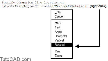
You can right-click for a shortcut to select either Horizontal, Vertical or Rotated options to explicitly specify a direction
– or you can imply a direction by where you pick for the dimension line location.
– pick above or below to imply a horizontal direction.
– pick right or left to imply a vertical direction.
9- Move your crosshairs near P1 and left-click to use this point for the dimension line location.

You supplied the extension line origin points (defpoints) using osnaps for this precise dimension.
– you can also use objects to supply these points automatically. – for example, press <enter> at the first origin prompt and then select a LINE to use the endpoints of the selected LINE.
10- Pick Dimension + Aligned. Press <enter> at the first prompt and then pick the LINE near P2 to use the endpoints of this LINE as the defpoints for this command. When you are prompted for the dimension line location pick near P3.

11- Pick Dimension + Linear. Invoke the Endpoint osnap shown & left click to use it as the first extension line origin.

Do not move your crosshairs too close to the osnap marker
– you may invoke an Endpoint osnap for the end of the dimension extension line instead of the Endpoint shown.
12- Invoke the Center osnap shown and left-click to use this as the second extension line origin point.
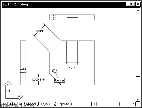
You may have difficulty invoking a Center osnap because there are so many Endpoint osnaps in this vicinity (cross inside CIRCLE).
– you can toggle the <Tab> key until you see the Center osnap marker then left-click to use this point.
13- Right-click in the drawing area to invoke a shortcut and select the Rotated option.
14- Invoke the Endpoint osnaps shown below and left-click to specify the rotation angle for the next dimension.

13- Pick near P1 at the prompt for the dimension line location to complete the Dimlinear command.

More practice?
16- Pick Dimension + Linear. For the first extension line origin use an Endpoint osnap near P2 & for the second extension line origin use an Endpoint osnap near P3. Then pick a point for the dimension line location to create the 1.000 dimension shown.
17- Pick Dimension + Continue and use an Endpoint osnap near P4 & press <enter> twice to terminate Dimcontinue.

When you use Dimcontinue you are not even prompted for the first extension line origin point.
– the second extension line origin of the previous dimension is used instead.
– you can also press <enter> at the first prompt instead to select the extension line of a different dimension to continue with.
18- Pick Dimension + Linear. For the first extension line origin use an Endpoint osnap near P1 & for the second extension line origin use an Endpoint osnap near P2. Then pick a point for the dimension line location to create the 2.000 dimension shown.
19- Pick Dimension + Baseline and use an Endpoint osnap near P3 & press <enter> twice to terminate Dimbaseline.

When you use Dimbaseline you are not even prompted for the first extension line origin point.
– the 1st extension line origin of the previous dimension is used.
– you can also press <enter> at the first prompt instead to select the extension line of a different dimension to use for the baseline.
On your own…
20- Create the remaining dimensions shown below on your own.

21- Save the changes to this drawing and Close the file.