How to create ELLIPSES & SPLINES (Introduction)
Here is How to create ellipses and splines in AutoCAD

You can create an ELLIPSE object using the Ellipse command and there are several different methods to create them.
- the default method lets you create an ELLIPSE by supplying any three end points of the major and minor axes.
- if you know the center point and an one end point of each axis you can use the Center option instead.
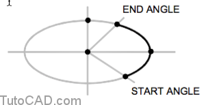
- you can create part of an ELLIPSE using the Arc option (or you can use the Trim command on a full ELLIPSE instead).
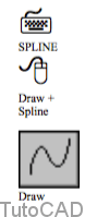
- You can create free form shapes using the Spline command.
- For example, you could draw contour lines as SPLINEs in a site plan by snapping to existing POINT objects using a Node osnap.

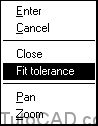
If the SPLINE should pass through all points (e.g. if you use an equation to generate points) then Fit tolerance should be zero
- but you can increase the Fit tolerance and allow the SPLINE to follow a path that is smoother if you prefer.
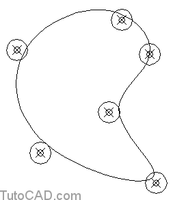
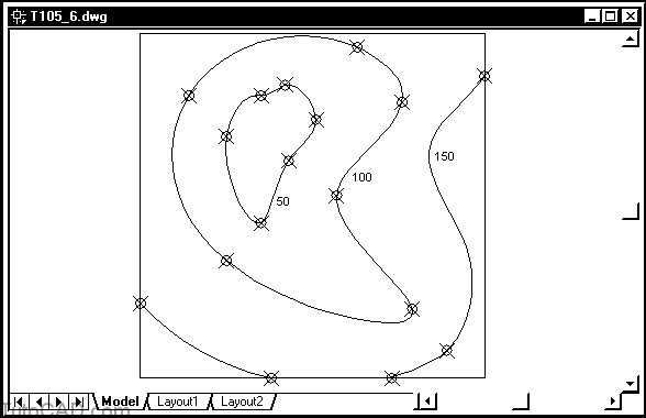
For example, the SPLINE below was created using the same points as the one shown above but with a Fit tolerance of 50 (instead of 0)
- CIRCLEs (with a radius of 50) are centered on each point to show that the SPLINE does pass through this tolerance zone.
SPLINEs are a very powerful object and there is much more to this object type than what is shown here
- but you can use Spline to sketch simple shapes without having to master all of the options for this command.
- You may want to learn more about Spline on your own later on.
PRACTICE : CREATING ELLIPSES AND SPLINES TUTORIAL IN AUTOCAD
1) Open the T105_5.dwg drawing in your personal folder.

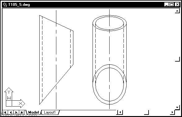
This is a drawing of a pipe that will be welded between two flat plates to provide a connection between two reservoirs.
Your drawing should look like this illustration after you have completed this exercise.
You will add the missing ELLIPSEs in the side view and then erase the green construction lines.
2) Right-click on the OSNAP status bar button and select Settings. Verify that Intersection & Node osnaps are selected & that Object Snap On is checked. Then pick OK.
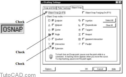
You will use Intersection osnaps in the first part of this exercise & then use Node osnaps in another drawing later on.
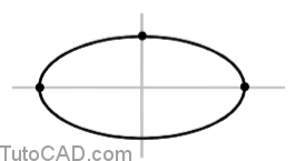
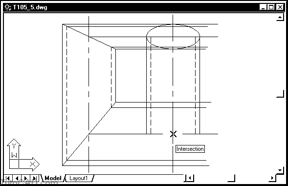
3) Pick Draw + Ellipse + Axis,End. Invoke the Intersection osnap shown & left-click to use it as an axis end point.
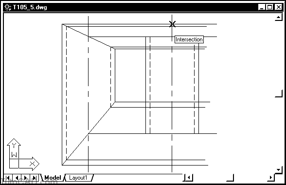
4) Invoke the Intersection osnap shown and left-click to use this as the other end point for the first axis.
You have just supplied two end points for one axis of an ELLIPSE.
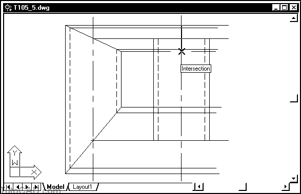
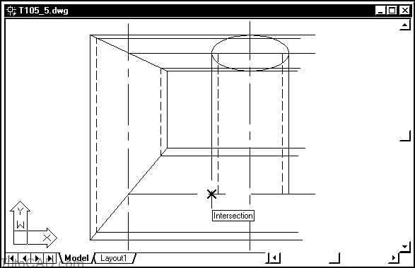
- AutoCAD now knows that the center point for this ELLIPSE is mid way between these two points.
- the orientation of the ELLIPSE is also now known.
- AutoCAD will have enough information to create the ELLIPSE when you supply another end point for the other axis.
5) Invoke the Intersection osnap shown and left-click to use it as an end point for the other axis.
à 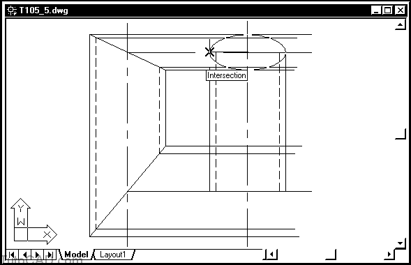
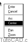
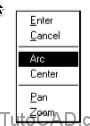
6) Pick Draw + Ellipse + Center. Invoke the Intersection osnap shown and left-click to use this as the center of the next ELLIPSE.
When you invoke Ellipse using a specific method from the pulldown menus AutoCAD automatically supplies responses to prompts
- in this last step AutoCAD supplied the _c response to use the Center option.
- you could use Ellipse manually and select these command line options yourself.
- selecting different methods to use Ellipse from the pulldown menu is similar to selecting methods for Arc or Circle.
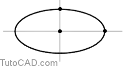
7) Invoke the Intersection osnap shown and left-click to use it as the end point of an axis.
8) Invoke the Intersection osnap shown and left-click to use it as the end point of the other axis.
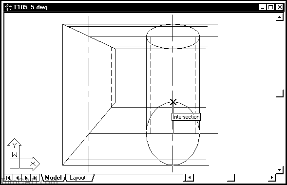
You have create two ELLIPSEs to represent the outer edges of this pipe in the side view.
- you used the default method (Axis,End) to create the first ELLIPSE and the Center method to create the second ELLIPSE.
- the method you choose will depend on which points are easier for you to supply.
The new Tracking tool in AutoCAD 2000 lets you supply points in commands like this without having to create construction lines.
9) Create the remaining ELLIPSEs shown on your own. Then select the green construction lines when no other command is running and press the Delete key to Erase them.
10) Save your changes to T105_5.dwg then Close this file.
11) Open the T105_6.dwg drawing in your personal folder.
12) Pick Draw + Spline. Invoke a Node osnap shown below near P1 (on one of the red POINT objects) at the prompt for the first point. Then use Node osnaps at POINT objects near P2, P3, P4, P5 and P6 but do not terminate this command.
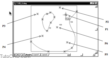
There are 6 red POINT objects that lie on the contour line that you are about to create as a SPLINE object.
13) Right-click in the drawing area to invoke a shortcut. Select Fit Tolerance and enter 0 for this value. Right-click in the drawing area again and select Close. Then press <enter> to use the default tangent direction and complete the SPLINE.
14) Pick the Undo button in the standard toolbar to undo the last SPLINE object.
15) Use Spline again to create a SPLINE with the same points but this time set Fit Tolerance to 50 (meters).

When Fit Tolerance is zero the SPLINE goes through every point
- when you use a non-zero Fit Tolerance the curve becomes smoother but the SPLINE does NOT pass through all points.
You do NOT have to Close SPLINE objects.
- press <enter> instead of using the Close option and you are prompted to pick tangent directions at the start & end points.
- Save your changes to T105_6.dwg.