How to use External Reference Files XREF
AutoCAD XREF explained (External Reference Files): free tutorial
Attaching a reference file to the host (active) drawing with Xref is like using Insert to insert that drawing file
- except the current version of the reference file is reloaded into the host every time you Open the host.
- whereas after you Insert a drawing file into another drawing the original file that was inserted is no longer used or required.
- You can use reference files in any assembly drawing (host) that references component drawing files (xrefs).
- changes to component files are automatically reflected in the assembly (host) drawing.
- you can even attach a reference of the entire assembly (host) in component files to help design the components.
- You can attach a reference file and then detach it without leaving behind unreferenced blocks or layers from the reference file.
- whereas if you Insert a drawing into another drawing you could potentially create a “mess” that is difficult to clean up.
- You do not have to worry about duplicate names (e.g. of layers, blocks, text styles, etc..)
- AutoCAD automatically adds a prefix to named symbols in reference files so they are unique in the host.
- Assembly drawings contain only enough information about reference files to load them properly into the host.
- the disk space required for a host file that is closed can be less than what would be required if reference files are not used.
- there is no duplication of information so there is no question as to which version is the “real” version.
Disadvantages
- Using reference files effectively requires proper coordination and standards to maintain an organized database of drawings.
- completed projects must be carefully archived to include all reference files.
Practice : using XREF tutorial in AutoCAD
1- Close all open drawings (if there are drawings open).
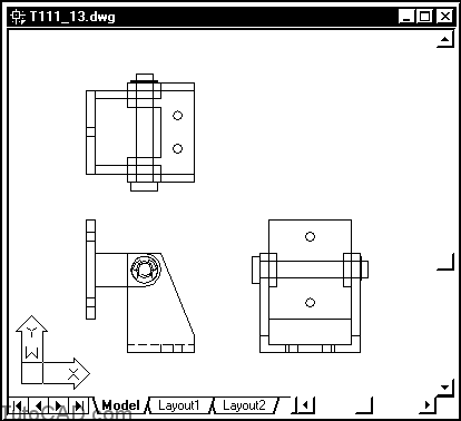
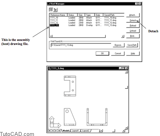
2- Open the T111_13.dwg drawing in your personal folder.

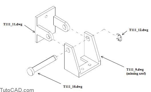
This 2D drawing is an assembly (host) that is already referencing three component drawing files.
– you will use Xref to attach the missing xref in T111_9.dwg. – the 3D exploded assembly illustration below shows the same components from an isometric viewing angle.
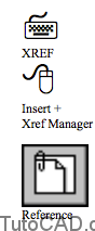
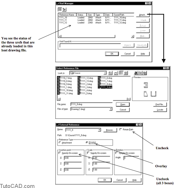
3- Pick Insert + Xref Manager. Pick the Attach button and select the T111_9.dwg in your personal folder and pick Open to continue. Uncheck ALL Specify On-screen boxes. Uncheck Retain path. Select Overlay as the reference type and then pick OK.
You can also use Xattach directly to attach an xref.
– if you pick Insert + External Reference you can avoid the Xref Manager dialogue box.
This drawing was created so that it could be inserted using (0,0) for the insertion point.
The Overlay Reference Type is practical when your references are only one level deep (the files you reference are not host files too)
-
- -because when you use the Overlay option any nested xrefs (reference files attached to reference files) are ignored.
- -this eliminates the possibility of having circular references (reference a file that is already referencing the host file).
If you uncheck Retain Path you can keep all project files in the same folder and then move them to a different folder later on.
– whereas when you check Retain Path it is difficult to move files or change folder names later on.
4- Pick File + Save. Pick File + Close to close the T111_13.dwg drawing.
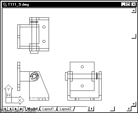
5- Open the T111_9.dwg drawing file in your personal folder. Pick Modify + Stretch. Left-click near P1 then near P2 to
6- invoke the implied Crossing tool shown & press <enter>.

7- Enter 0,0.5 as the base point or displacement then press <enter> at the second point prompt.
8- Use a similar technique to stretch the side view by 0.5.

9- Pick Insert + External Reference. Select T111_13.dwg in your personal folder then pick Open to continue. Pick OK.

You just attached a reference of the assembly drawing inside this component drawing and it is obvious that the components do not fit together now.
The other components were attached to T111_13.dwg using the Attachment Reference Type option
- – so these xrefs are now nested xrefs in this drawing file.
If you had used the Attachment Reference Type in step 3 you would have had an error message here (circular reference)
– because you would have been attaching a reference file that was already referencing the current drawing.
10- Pick Insert + Xref Manager. Select the T111_13.dwg Xref and then pick the Detach button (this will also detach the other nested xrefs that are attached as Xrefs to this file). Pick OK to exit Xref.
11- Pick File + Save.
12- Pick File + Close to close this component file.
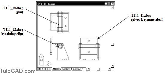
13- Open the T111_13.dwg assembly in your personal folder.
When you open the assembly drawing, the latest version of component drawings will load automatically. You can see that these components do not fit together anymore.

More practice?
14- Close the current assembly drawing.
15- Use Stretch & Move to modify the three other component drawing files to match the wider T111_9.dwg component. The drawing file names are indicated below for your convenience. Verify that these components fit together in the T111_13.dwg assembly drawing when you are finished.
16- Save your changes and Close all files.
You have used reference files in a simple but practical example but there is much more to learn about this powerful AutoCAD feature.
– use AutoCAD Help on Xref for a long list of useful information.