How to use linetypes & Drawing Scale
Here is how to use linetypes & Drawing Scale
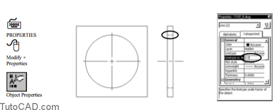
You can assign a Linetype BYLAYER to 2D objects (LINEs, ARCs, CIRCLEs etc..) using the Layer dialogue box.
- left-click on the Linetype currently assigned to the desired layer to invoke the Select Linetype dialogue box.
- if the desired linetype is not displayed in the Select Linetype dialogue box you can pick the Load button to load it.
- when you create New drawings from scratch the ONLY loaded linetype is CONTINUOUS (the default linetype).
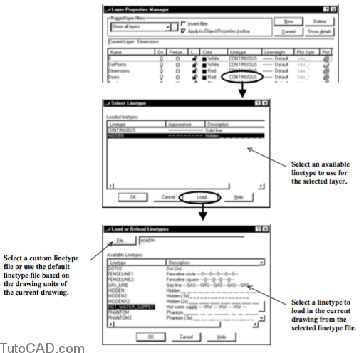
- Acad.lin is the default linetype file when the MEASUREMENT system variable is 0 (English defaults).
- linetypes stored in this file are scaled for drawings in which a drawing unit represents one inch.
- Acadiso.lin is the default linetype file when the MEASUREMENT system variable is 1 (Metric defaults).
- linetypes stored in this file are scaled for drawings in which a drawing unit represents one mm.
- Use the Linetype command to invoke the Linetype Manager.
- the Load button in this dialogue box is the same as the Load button in the Select Linetype dialogue box (see previous page).
- use Delete to remove linetypes in the current drawing (you cannot delete linetypes used on objects or assigned to layers).
- select any linetype to be Current (normal CAD practice is to leave Current Linetype set to ByLayer).
- use the built-in Linetype filters & select Show all used linetypes to reduce the number of linetypes displayed in the list.
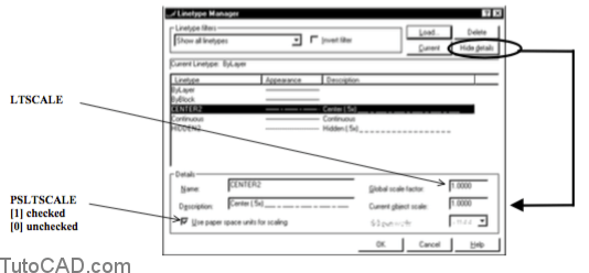 If you Hide details then you will not have access to two important system variables that affect linetype scale.
– PSLTSCALE [Use paper space units for scaling]
– LTSCALE [Global scale factor]
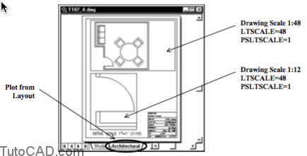
When you Plot from Layouts you can get acceptable linetype scales if you leave linetype scale settings at their default values.
- -check Use paper space units for scaling (PSLTSCALE=1)
- -set Global scale factor to 1.0 (LTSCALE=1)
- -then linetypes will use the same (reasonable) linetype scale for all drawing scales.
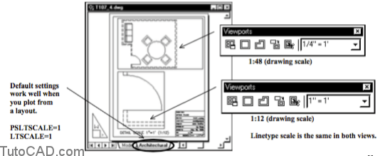
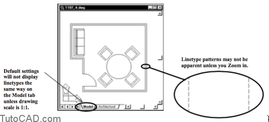
- Linetype scale for objects displayed from the Model tab (with these defaults) will match objects displayed in Layouts at 1:1 scales
- – but for larger or smaller drawing scales the linetype scale on the Model tab will NOT match linetype scale on Layouts.
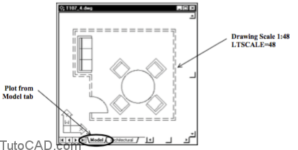
- – all linetypes can appear CONTINOUS for large (e.g. 1:48) scales (you would have to Zoom in to see linetype patterns).
- – linetypes can also appear CONTINUOUS for small (e.g. 10:1) scales when lines are not long enough to display a pattern.
Setting LTSCALE for the Model tab
If you want to Plot from the Model tab you must adjust LTSCALE for all drawing scales other than 1:1.
– the following table illustrates how you can adjust LTSCALE appropriately for different drawing scales.
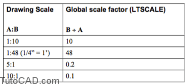
linetypes for very large or small drawing scales will look CONTINUOUS on Layouts when PSLTSCALE=1.
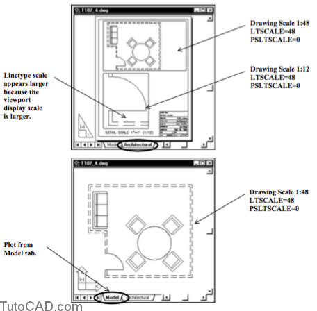
If you optimize LTSCALE for the Model tab you might want to Uncheck Use paper space units for scaling (PSLTSCALE=0).
- -then viewports in Layouts will display linetypes without scaling the patterns to compensate for view magnification.
- -but layouts with multiple viewports at different drawing scales (e.g. details) will have different linetype scales in each view.
- -LTSCALE is global so linetype scale would only be ideal for viewports at one drawing scale when PSLTSCALE=0.
Linetype scales may not reflect changes made to LTSCALE until a view regenerates (e.g. when you Open or Plot the drawing.)
– you can force AutoCAD to display linetype scale correctly in all viewports by invoking Regenall.
Linetype scale for individual objects
- LTSCALE is a global scale that applies to all objects in a drawing. – each object also has an individual linetype scale factor and the default linetype scale factor for each new object is 1.0.
- – the linetype scale of objects is the product of LTSCALE with the individual linetype scale factor assigned to objects.
- In some cases it could be desirable to make minor linetype scale factor adjustments to some selected objects.
- – for example, you may have to reduce the linetype scale of short lines to force a linetype pattern to appear.
- – you can change the linetype scale factor of selected objects without changing linetype scale of other objects in the drawing.
- – you will learn how to change properties for selected objects later on in the Using The Object Properties Manager section
Do not change Current object scale (CELTSCALE) in the Details area of the Linetype Manager
– use 1.0 (the default object scale) for new objects.
– if some objects require minor adjustments you can select them
and change only the individual linetype scale of those objects.
practice assigning linetypes BYLAYER
- Close the drawing from the previous exercise (if it is open).
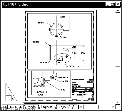
- Open the T107_3.dwg drawing file in your personal folder.
This 2D drawing of a coffee cup is set up to plot from a layout.
Layers are already created for Center lines and Hidden lines. Objects are already created on these layers.
In this exercise you will assign appropriate linetypes to layers.
- Pick Format + Linetype. Make sure the Details area is displayed (if details are not displayed pick Show details). Global scale factor should be 1.0 (LTSCALE) & Use paper space units for scaling should be checked (PSLTSCALE=1). Remain in this dialogue box for the next step.

Drawings created from scratch will only have the CONTINUOUS linetype loaded (defined).
– you must load the desired linetypes into the current drawing before you can assign them to a layer.
- Pick the Load button in the Linetype Manager dialogue box. Scroll down the list and select HIDDEN2 from the Available linetypes in the default acad.lin file. Pick OK to return to the Linetype Manager dialogue box then pick OK to complete the Linetype command.
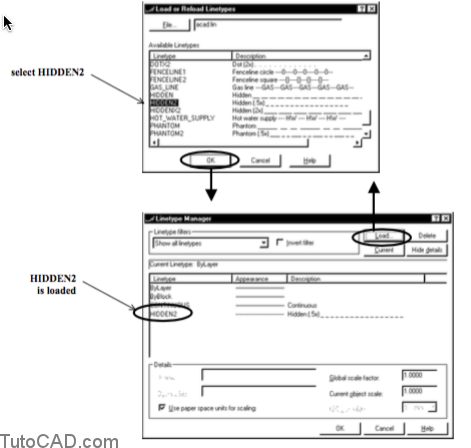
The HIDDEN2 linetype is half the scale (twice as many line segments in the same length) of the HIDDEN lineytpe.
– this linetype will display on shorter lines compared to the HIDDEN linetype which is practical for mechanical drawings.
– there is also a HIDDENX2 which is twice the scale of HIDDEN. – several other standard linetypes (e.g. CENTER, DASHED, etc..)
also have these corresponding 2 and X2 related linetypes.
- Pick Format + Layer. Left-click on CONTINUOUS for the Hidden Lines layer to invoke the Select Linetype dialogue box. Select the HIDDEN2 linetype that you loaded. Pick OK to return to the Layer dialogue box & pick OK to exit Layer.

- Use Zoom to display the (blue) Hidden Lines in both viewports at a higher magnification and observe the linetype pattern assigned to objects on this layer.
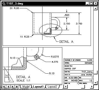
Even though these viewports use different display magnifications (1:2 for the main viewport and 1:1 for the Detail A viewport)
– the linetype scale for Hidden Lines is the same in both viewports.
– LTSCALE & PSLTSCALE are currently set to use the default values for drawings created from scratch.
More practice ?
- Assign the CENTER2 linetype to the Center Lines layer.

- Save your changes to T107_3.dwg & Close this file.