How to make Block Definitions
Free course how to create a Block in AutoCAD
You can easily create new block definitions with Bmake.
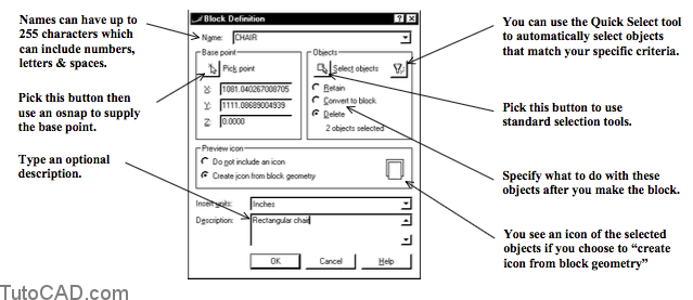
- begin by typing a Name for the new block definition that is unique in the current drawing.
- then pick the Select objects button and use selection tools to select objects for the block.
- pick the Pick point button and use osnaps to select an appropriate base point relative to the selected objects.
- the block definition is stored in the current drawing file.
- Blocks & drawing files can have insert units assigned to them.
- insert units are used when you drag & drop drawings or blocks into the active drawing using AutoCAD DesignCenter.
- if the insert units of the active drawing are different than the block or drawing being inserted, the insert is scaled appropriately.
- for more information use AutoCAD Help for INSUNITS.
- You will be learning more about AutoCAD DesignCenter later in this document.
Practice : How to create a block tutorial in AutoCAD
- Launch AutoCAD (if it is not already running). Close all open drawings (if there are drawings open).
- Open the T111_1.dwg drawing in your personal folder.
- Pick Tools + Run Script. Select your personal folder to Look in and select T111.scr as the script File name. Then pick the Open button to run this script. This sets drafting tools to match the behavior described in the exercises.
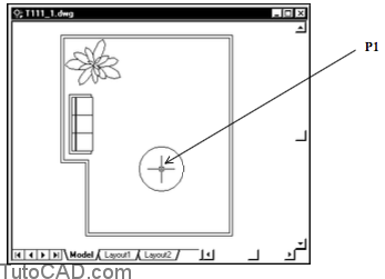
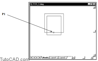
- Pick Draw + Circle + Center,Diameter and pick a point near P1 as the center point. Enter 60 as the diameter.
This CIRCLE represents a table and you will create a block definition called TABLE in this drawing.
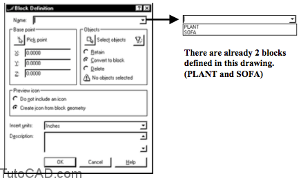
5- Pick Draw + Block + Make. Click on the Name drop-down arrow to examine the blocks already defined in this drawing file but do not select one of these blocks.
6- Type TABLE as the Name. Pick the Select objects button and select the CIRCLE you created in step 4. Press <enter> to return to the Block Definition dialogue box.
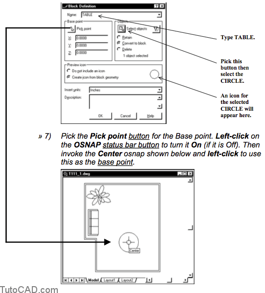
The base point is used when you Insert block definitions later on so you should select a logical point relative to the selected geometry
- osnaps are normally used for precise points when you create drawing symbols as blocks.
8- Type a description for this block definition such as Round 60 inch diameter table. Select the Delete radio button then pick OK to complete the Bmake command.
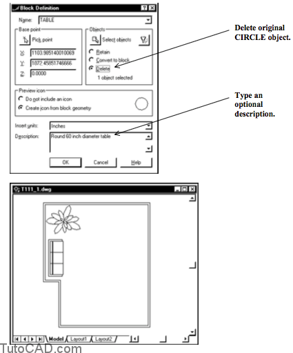
- You selected Delete so the original object is erased.
- you could have left the default setting as Convert to block but that block insert would have been on the current Layer 0. – if you select Retain the CIRLCE is kept (as a CIRCLE). – the TABLE block will be inserted in the next exercise.
- You created the CIRCLE on Layer 0 so you can take advantage of the special block properties of this layer.
- when you Insert a block defined from objects on Layer 0, the insert will inherit properties (e.g. Color) of the current layer.
9 Pick Draw + Rectangle. Pick any point P1 for the first corner and enter @32,32 for the other corner of the rectangle.
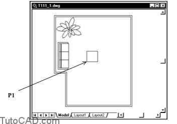
10- Pick Modify + Offset. Enter a distance of 4 and select the rectangle. (you may want to toggle OSNAP Off now) Then pick a point inside the rectangle as the side to offset and press <enter> to terminate Offset.
11- Right-click in the drawing area to invoke a shortcut and select Zoom. Drag your cursor upwards to zoom in on the two rectangles. (you may want to right-click again to select Pan then pan the rectangles to the center of the screen). Then press <Esc> to exit Zoom Realtime.
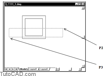
12- Pick Modify + Stretch. Hold your pickbox near P2 such that it is not above any objects and left-click. Move your crosshairs near P3 to invoke the implied Crossing tool shown and left-click to select the two rectangles.. Press <enter> to continue. Enter 0,–8 as the displacement and press <enter> at the prompt for the second point.
The Crossing box should include end points of the inner rectangle but NOT include endpoints of the outer rectangle.
You want to stretch only the inner rectangle and leave the outer rectangle as it is.
13- Pick Modify + Trim. Press <enter> at the first prompt to use all objects as cutting edges. Then pick the edge of the rectangle near P1 as the object to trim and press <enter> to terminate Trim.
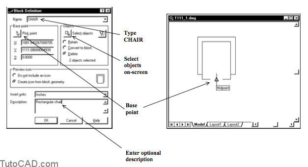
14- Pick Draw + Block + Make. Use a similar technique to define a block called CHAIR from the two objects on-screen. When you supply the base point, press & hold <shift> while you right-click in the drawing area to invoke a shortcut and select the Midpoint osnap. Then hold your crosshairs over the bottom edge to invoke the Midpoint osnap shown.
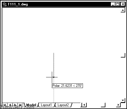
15- Left-click on the POLAR status bar button to turn this tool On (if it is Off).
16- Pick Draw + Line and pick any point near the center of the screen as the start point. Move your crosshairs downward to invoke a 270 degree tooltip angle. Type 1 as the distance and press <enter>. Press <enter> again to complete Line.
Now for a door…
17- Right-click in the drawing area to invoke a shortcut and select Zoom. Then drag your cursor upward to zoom in on the short LINE you just created. (You may also have to right-click to use Pan if it is not in the center of the screen.) Then press <Esc> to terminate Zoom Realtime.
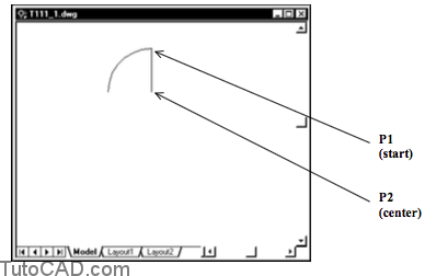
18- Pick Draw + Arc + Start,Center,Angle. Invoke an Endpoint osnap at the top of the LINE near P1 & left-click to use this as the Start point. Invoke an Endpoint osnap at the bottom of the LINE near P2 & left-click to use this as the center point. Then enter 90 as the Angle to create an ARC.
You just made a door that is 1 drawing unit wide.
Next you will use these objects to define a block called DOOR.
When you Insert the DOOR later on you can make it the any door size by changing the insertion scale.
19- Pick Draw + Block + Make. Use a similar technique to define a block called DOOR from the two objects on-screen. Use the illustrations below as a guide.

20- Zoom Previous until you get back to the original view.
You have created three new block definitions in this drawing but there are no insertions.
21- Save this drawing for the next exercise.