How to use MIRROR command
Here is a free course how to use Mirror command in AutoCAD
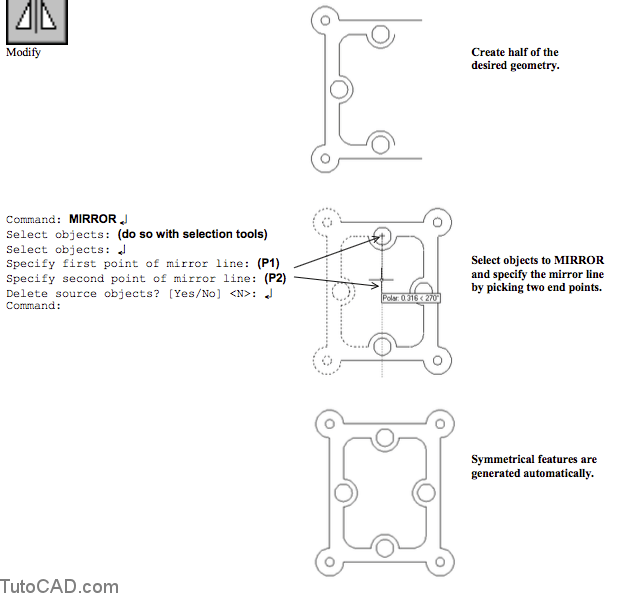
Most designs are symmetrical in some way and you can save CAD construction time if you recognize this symmetry.
- use Mirror to automatically generate symmetrical features after you create the original features.
- this can save time & avoid potential errors that could be introduced by re-creating the symmetrical geometry manually.
Delete Source Objects
- You can use Mirror to convert left side parts to right side parts or Mirror house/building plans to generate alternative designs. - when you use the Mirror command to generate a new design you can select the option to delete source objects.
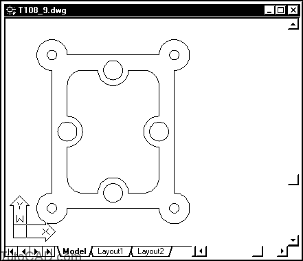
- In the example below you could design the left-side end plate and then use Mirror to create the matching right-side plate automatically.

- In the example below you could design the floor plan for a home or office and use Mirror to create an alternative design automatically.

- You can Mirror TEXT to mirrored locations but generate TEXT that is readable (not mirrored) if the MIRRTEXT system variable is 0.

Practice : How to use MIRROR command tutorial in AutoCAD
- Close the drawing from the previous exercise if it is open.
- Open the T108_9.dwg drawing in your personal folder.
- Check your status bar buttons to make sure that OSNAP and POLAR are both On. (left-click on them if they are off).
![]()
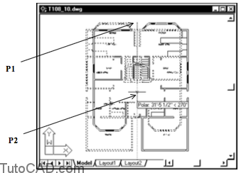
- Pick Modify + Mirror. Hold your pickbox near P1 so that it is not above any objects and left-click. Then pick near P2 to select objects (shown highlighted in the bottom illustration) using an implied Window. Then press <enter> to continue.
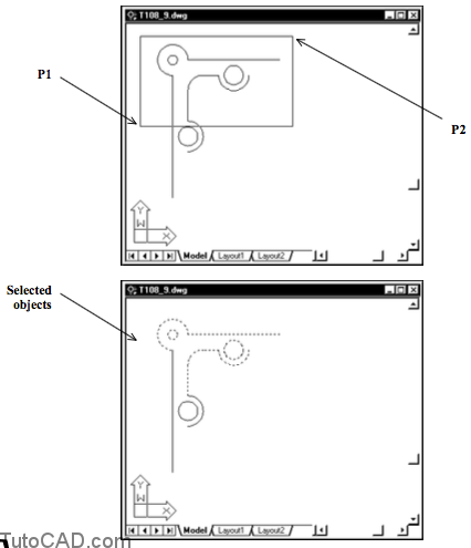
Picking left to right invokes an implied Window.
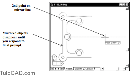
- Hold your crosshairs over the CIRCLE to invoke the Center osnap shown at the prompt for the first point on the mirror line then left-click to use that point.
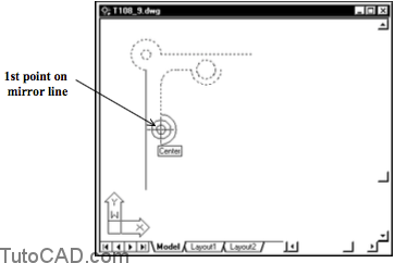
- Move your crosshairs to the right and left-click when the Polar tooltip angle is 0 degrees to use this point as the second point of the mirror line. Press <enter> to respond <N> at the delete source objects prompt. The command line history of the entire command is shown.
Command: _mirror
Select objects: (use implied WINDOW as shown on previous page)
Select objects: ↵
Specify first point of mirror line: (invoke CENTER osnap shown)
Specify second point of mirror line: (pick point to the right with POLAR tooltip angle=0)
Delete source objects? [Yes/No] <N>: ↵
Command:
- Use a similar technique to complete the design.
- Save changes to this drawing and Close the file.
- Open the T108_10.dwg drawing in your personal folder.
- Type MIRRTEXT on the command line and enter 0 as the new value.
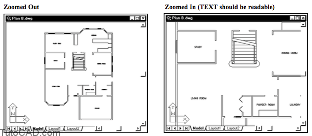
- Pick View + Zoom + In so you can read the TEXT labels in this drawing. Then pick View + Zoom + Out.

TEXT objects in each room are in the proper orientation to be read (they are NOT mirrored).
- Pick Modify + Mirror. Enter ALL when prompted to select objects and press <enter> again to signal AutoCAD that you have selected all objects to Mirror.
- Left-click on the OSNAP button in the status bar to toggle this setting Off.
![]()
- Pick any point near the top of the screen near P1 as the first point of the mirror line. Then move your crosshairs downward and left-click when the POLAR tooltip angle is 270 to use this point as the second point of the mirror line. Right-click in the drawing area to invoke a shortcut and select Yes at the prompt to delete source objects.

If you had left OSNAP turned On you may have had difficulty in selecting a point that was directly below the first mirror line point.
– when OSNAP gets in your way you can toggle it Off (even if you are in the middle of a command).
– the same running osnap modes are available when you toggle OSNAP back On again.
- Pick File + Save As and use Plan B.dwg as the new name in your personal folder.
- Pick View + Zoom + In to verify that the TEXT labels are still in the proper orientation to be read (not mirrored).
More practice?
- Save the changes to this new drawing & Close the file.
- Open the T108_11.dwg drawing in your personal folder.
- Saveas this file as Right side.dwg in your personal folder.
- Use Mirror to generate the matching design of the left side end plate saved in this drawing (see illustration on page 42). The desired end results for the right side plate is shown.
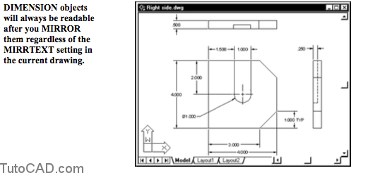
- Save the changes to this new drawing and Close the file .