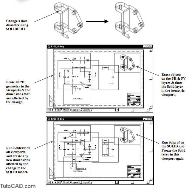
Updating Changes To SOLIDs in 3D drawing
SOLIDs and their generated 2D drawings (made with Soldraw & Solprof) are not associative
- drawings will not match modified SOLIDs unless you use Soldraw or Solprof again to update the drawing.
PRACTICE UPDATING CHANGES TO SOLIDs
» 1 Open the T305_8.dwg file in your personal folder.
» 2) Left-click on the Model tab to switch to the model.
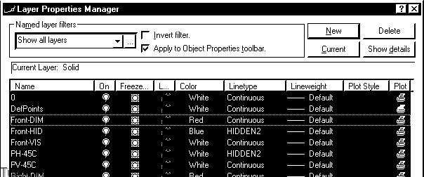
3) Select Solid in the Layer drop-down list on the Object Properties toolbar to make it the current layer.
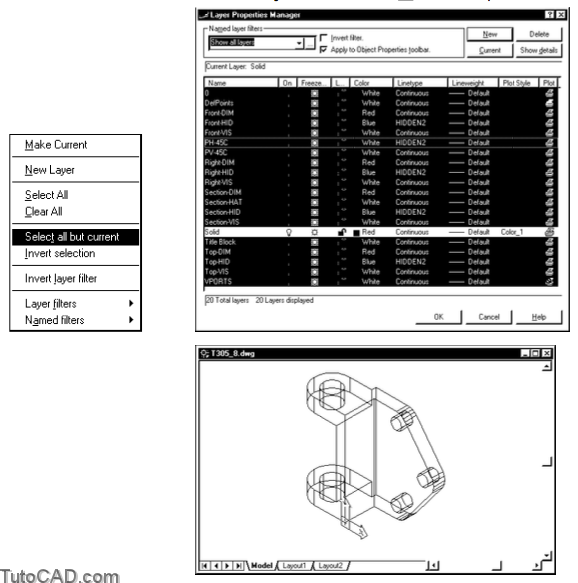
4) Pick Format + Layer. Right-click in the layer list of this dialogue box to invoke a shortcut and pick Select all but current. Left-click on a lightbulb icon for one of the selected layers to turn them all Off. Then pick OK.
5) Pick Modify + Solids Editing + Offset Faces. Select the isolines of the two large holes shown highlighted below and press <enter> to continue. Enter positive 0.25 to make the hole 0.5 inches smaller in diameter. Press <enter> twice to terminate Solidedit.

6) Pick Format + Layer. Right-click in the layer list to invoke a shortcut and pick Select All. Left-click on the light-bulb icon for one of the selected layers to turn them all back On.
7) Right-click in the layer list again to invoke a shortcut and select Clear All. Then select layer 0 (zero) and pick the Current button to make this the current layer.
8) Select the Dimensions named layer filter. Right-click in the layer list to invoke a shortcut and pick Select All. Left-click on one of lightbulb icons for one of the selected layers to turn them all Off.

9) Select the Show all layers named layer filter. Left-click on the lightbulb icon for the Solid layer to turn this layer Off. Then pick OK to complete your changes to layer settings.
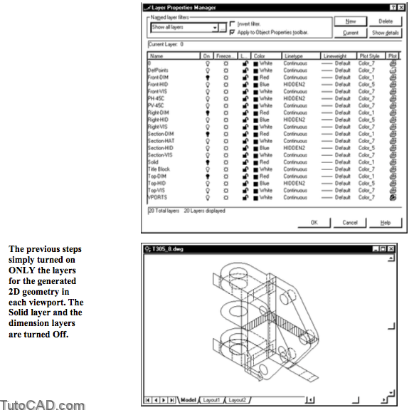
10) Pick Modify + Erase. Select all visible objects on screen with an implied Window then press <enter> to delete these objects.
11) Pick Format + Layer. Right-click in the layer list to invoke a shortcut and pick Select All. Left-click on one of the lightbulb icons that are Off to turn all layers back On. Then pick OK.
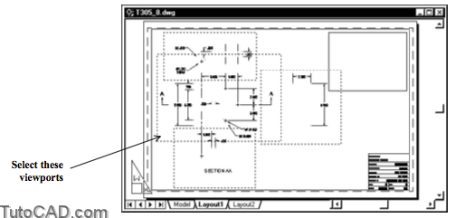
12) Left-click on the Layout1 tab to switch back to this layout.
13) Pick Draw + Solids + Setup + Drawing. Select the 4 viewports shown highlighted below and press <enter> to terminate Soldraw.
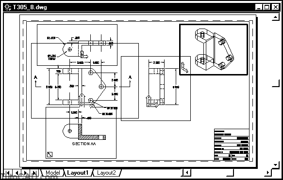
14) Double-click in the isometric viewport to activate it.
15) Pick Format + Layer. Select the Solid Layer and scroll over to the Active viewport column (if required) then left-click on the icon there to Thaw this layer in the active viewport. Pick OK to complete the change.
16) Pick Draw + Solids + Setup + Profile & use the command line history below as a guide to generate a profile.
Command: SOLPROF↵
Select objects: (pick the SOLID in the active viewport)
Select objects: ↵
Display hidden profile lines on separate layer? [Yes/No] <Y>: ↵
Project profile lines onto a plane? [Yes/No] <Y>: ↵
Delete tangential edges? [Yes/No] <Y>: ↵
One solid selected.
Command:
17) Left-click in the Top viewport to activate it.
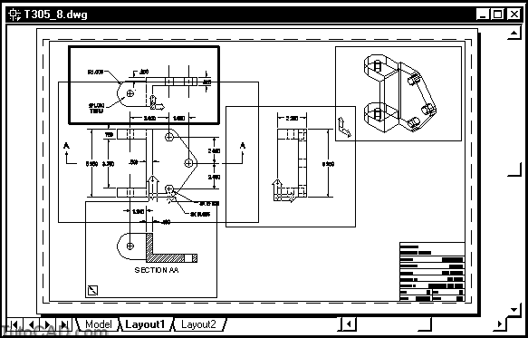
18) Pick View + Zoom + Window to zoom into this viewport.
19) Pick Modify + Erase. Select the dimension near P1 andpress <enter> to delete it.

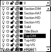
20) Drop down the Layer list on the Object Properties toolbar and select Top-DIM as the new current layer.
21) Pick Dimension + Diameter. Pick the CIRCLE near P1 then pick near P2 to create the new updated dimension.

22) Pick View + Zoom + Previous.
23) Left-click in the isometric viewport to activate it.
24) Pick Format + Layer. Select the Solid Layer and scroll over to the Active viewport column (if required) then left-click on the icon there to Freeze this layer in the active viewport. Pick OK to complete the change.

25) Left-click on MODEL in the status bar to switch back out to the PAPER (paperspace).
26) Save the changes to your updated drawing & Close the file.
More Practice
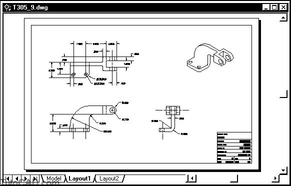
Open the T305_9.dwg file in your personal folder.
- this file contains the simple SOLID model shown below.
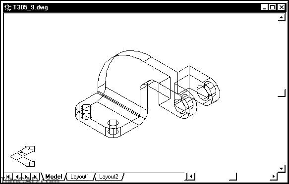
Develop a 2D drawing in Layout1 using the same techniques that you used in the exercises of this document.
- Insert the T305_3.dwg in your personal folder as the title block.
- drawing scale is 1:2
- create at least some dimensions in each view (no need to completely dimension the drawing) on appropriate layers.