Working Effectively With Attributes – overview
Overview
When you define a new Block you can select graphical objects like LINEs, ARCs, CIRCLEs & TEXT to use in the block definition
- so when you Insert the block you get an instance (copy) of the definition which is like an imprint of the original objects.
Attribute definitions (ATTRIBUTEs) are special objects that are like formatted database fields in which you can store (ASCII) text data.
- you can select ATTRIBUTEs along with other (graphical) objects when you define new Block definitions.
- then when you Insert the block you can enter different values (text strings) for the ATTRIBUTEs in each block insert.
Blocks with attributes are used extensively in AutoCAD for a variety of applications in industry & common examples are shown below.

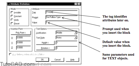
Define new ATTRIBUTE DEFINITIONs with the Attdef command.

- ATTRIBUTE DEFINITIONs have similar properties as TEXT objects such as the height, style, rotation & justification.
- you can specify the default value and the prompt used when you Insert a block containing this attribute definition.
- the tag is used to identify attributes later on so you should use a name that you will remember or recognize.
- pick the Pick Point < button to supply a point on-screen or the Insertion Point will be the drawing origin (0,0,0).
Check Invisible if you do not want attributes to be visible.
- you can override this setting with Attdisp and you will learn more about attribute visibility on page 20.
Check Constant if the attribute value must always be the same.
- the attribute becomes like a simple TEXT object but still retains special attribute properties (e.g. visibility controlled by Attdisp).
Check Verify if you want to double-check an attribute value when you insert a block that contains this attribute.
- if ATTDIA=0 you must enter the same attribute value twice.
Check Preset to automatically use the default value when you insert a block that contains this attribute.
- it is like checking Constant but you can change values later on.
PRACTICE CREATING NEW ATTRIBUTE DEFINITIONS
1) Launch AutoCAD (if it is not already running). Close all open drawings (if there are drawings open).
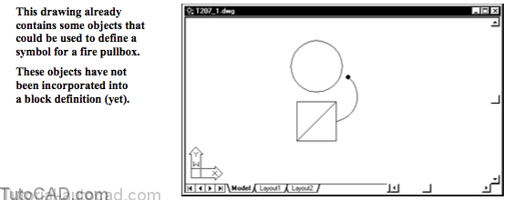
2) Open the T207_1.dwg drawing in your personal folder.
3) Pick Tools + Run Script. Select your personal folder to Look in and select T207.scr as the script File name. Then pick the Open button to run this script. This sets drafting tools to match the behavior described in the exercises.
4) Pick Draw + Block + Define Attributes. Type FTAG as the Tab, Fire Pullbox Type as the Prompt and F as the Value. Select Middle as the Justification and enter 3 as the Height. Then pick the Pick Point button to continue.

Notes is the current text style so this is selected by default.
5) Turn On the OSNAP in the status bar and invoke the Midpoint osnap shown below. Left-click to use this as the insertion point then pick OK to create the ATTRIBUTE DEFINITION object.

6) Pick Edit + Clear and select the diagonal LINE then press <enter> to delete this construction object.
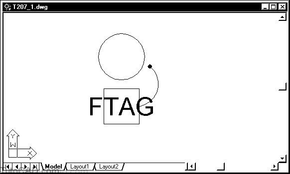
This ATTRIBUTE DEFINITION is not incorporated into a block definition (yet) so you see the Tag where the Value will be.
- these objects on-screen will be used to create a drawing symbol for a drawing at 1:48 scale (1/4 inch equals one foot).
- a text height of 3 will become 1/16 of an inch in the Plot.
» 7) Save the changes you made to this drawing to prepare forthe next exercise.