Creating New Layouts From Scratch
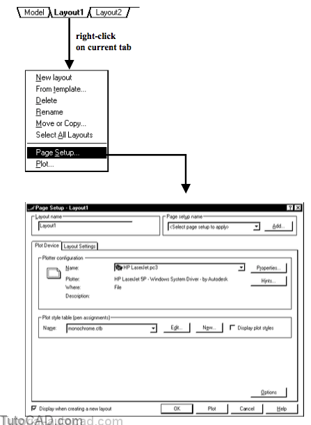
You can create a new layout from scratch by right-clicking on theModel or a Layout tab and picking New layout from a shortcut.
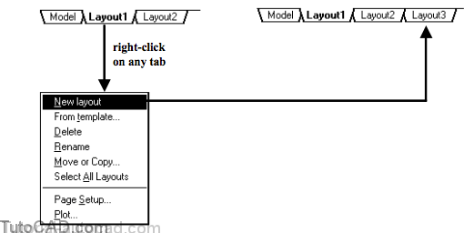
Creating a New layout does NOT make it the current layout
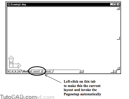
- and new layouts are not setup initially so when you select a new layout the Page Setup will be invoked automatically.
- the same thing happens if you select one of the existing layouts (Layout1 or Layout2) when you start a new drawing from scratch.
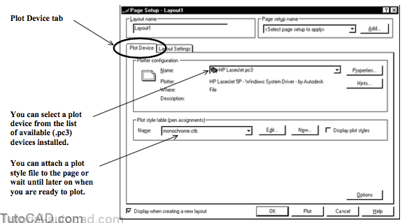
Select one of the devices from the available (.pc3) plot devices installed on your system in the Plot Device tab.
- this will have an effect on the available sheet sizes in the Layout Settings tab of the same Page Setup dialogue box.
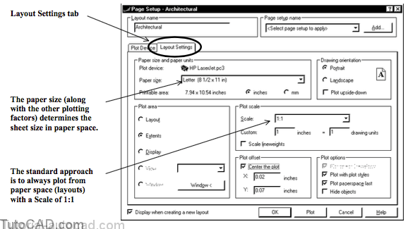
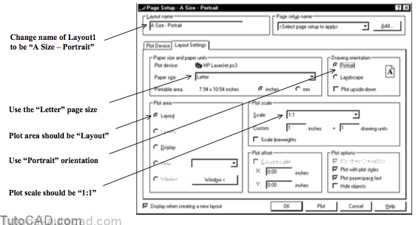
Set the main plotting parameters like Paper size, Drawing orientation, Plot scale & Plot area on the Layout Settings tab.
- layouts are like a Plot Preview in real time.
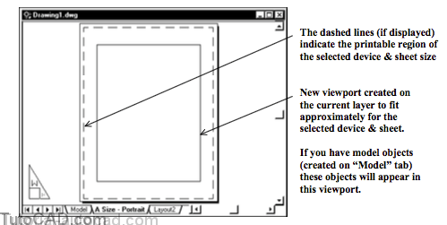
A new viewport may automatically be created for you on the current layer (to fit approximately on the page) of new layouts.
- you may also see a dashed margin around the sheet edge which indicates the printable region for the selected plot device.
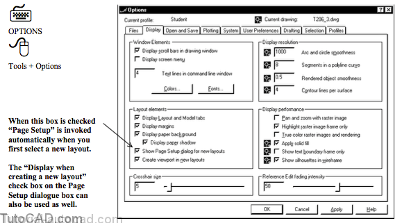
You can use Options to control whether or not new viewports are automatically created when you make new Layouts.
- you can also turn off other page display features for Layouts in the same Display tab.
- for example, you may want to turn off the dashed margin once you create a title block and position it properly on the page.

Changes you make to a layout in the Page Setup dialogue box are saved in the drawing file for that layout.
- you can return to the same Page Setup to change settings.
- make the desired layout the current layout and right-click on the layout tab to invoke a shortcut and select Page Setup.
You can use a Wizard to create layouts but (as you will discover in this module) it is easy enough to set up new layouts manually.
- pick Tools + Wizards + Create a layout from the pulldown menu to invoke a Wizard to help you create new layouts.
PRACTICE CREATING A LAYOUT FROM SCRATCH
» 1) Launch AutoCAD (if it is not already running). Close all open drawings (if there are drawings open).
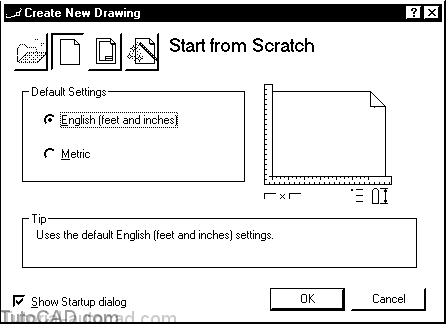
» 2) Pick File + New and select Start from Scratch. Select English as the default settings then pick OK to continue.
» 3) Pick Tools + Run Script. Select your personal folder to Look in and select T206.scr as the script File name. Then pick the Open button to run this script. This sets drafting tools to match the behavior described in the exercises.
» 4) Left-click on the Layout1 tab at the bottom of the screen to make it the current tab. You should automatically go to the Page Setup dialogue box (if not, then right-click on this tab again and select Page Setup).
5) On the Plot Device tab select the HP Laserjet device (or the device your instructor tells you to use instead) as the Name and then select Layout Settings tab.

6) Make the changes identified below & enter A Size – Portrait for the new name of this Layout. Then pick OK.
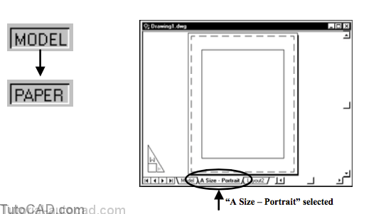
You are now in “paper space”.
- you see the edge of your page using the plot parameters that you specified in the Page Setup.
- if your page does not look like the illustration below you should verify the Display tab in Options (see page 7)
- the MODEL status bar button is now replaced by a PAPER status bar button.
- the Layout1 tab is now called A Size – Portrait.
7) Pick the Model tab (the MODEL button in the status bar is not displayed) to return back to “model space”.

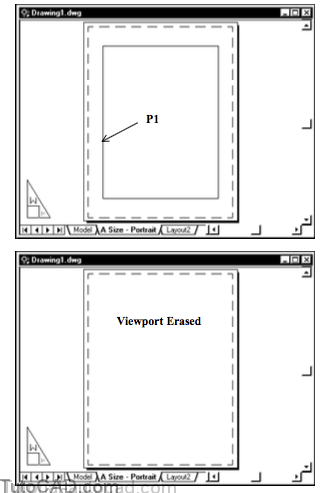
8) Select the Size A – Portrait tab again and double-click inside the inner rectangle near P1 below.
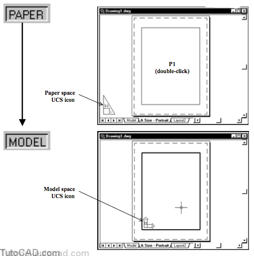
You can toggle spaces by simply double-clicking on the desired space.
- a viewport was created automatically when you created this layout.
- you can double-click in the desired viewport to make this the current viewport and then work in model space from the layout.
- if you double-click on the paper (outside any viewport) you return to paper space.
You can also toggle back and forth between MODEL and PAPER by left-clicking on these status bar buttons.
9) Double-click outside the inner rectangle near P1 below to switch back to the PAPER.
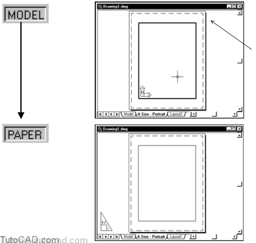
10) Toggle back and forth between MODEL and PAPER by left-clicking on these status bar buttons. Stop when you are back in PAPER.

You have several reminders as to which space you are in
- PAPER vs MODEL in the status bar buttons
- Model space vs Paper Space UCS icon
- Model vs Layout# as the selected tab.
11) Pick Edit + Clear. Select the viewport border near P1 and then press <enter> to Erase the viewport.
12) Pick File + Save. Change the Save as type to AutoCAD Drawing Template File (*.dwt) and Save in to your personal folder. Then enter My template for layouts as the File name and pick the Save button.

13) Enter a description and then pick OK to create a template file that will be used in the next exercise.

- You have created a template file that has a customized layout and you will use the layout from this template in the next exercise.