Finding Drawings With Attributes In DesignCenter
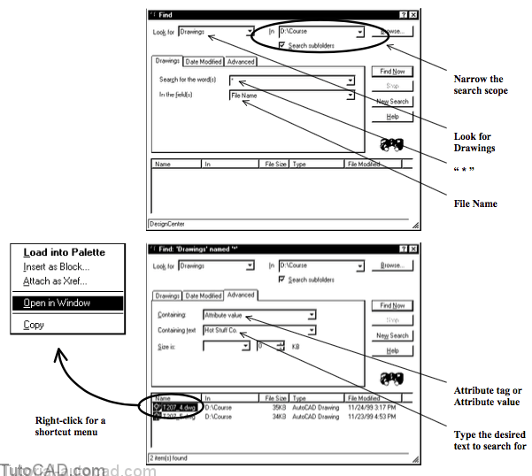
You can use AutoCAD DesignCenter to Find drawings that contain either specific Attribute Tags or specific Attribute Values.

- Search for the word(s) cannot be blank on the Drawings tab but you can enter * (the wildcard for all file names).
- specify your attribute criteria on the Advanced tab.
- pick Find Now to find all drawings that match the current criteria.
- right-click on a drawing file found by the search to invoke a shortcut & select Open in Window to open that drawing.
USING DESIGNCENTER TO FIND DRAWINGS WITH SPECIFIC ATTRIBUTE VALUES
» 1) Close all drawings from previous exercises.
» 2) Start a New drawing from scratch using English default settings.
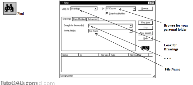
» 3) Pick Tools + AutoCAD DesignCenter to launch this tool if it is not already running.
» 4) Pick the Find button in the AutoCAD DesignCenter. Pick the New Search button to clear the previous search results (if any). Pick the Browse button and select your personal folder then pick OK to return to DesignCenter. Verify that Drawings is selected in Look for. Type * in the Search for word(s) and verify that File Names is selected in the field(s). Then pick the Advanced tab to continue.
If you want to restrict the search to drawings created in a specific time frame you can specify this criteria on the Date Modified tab.
- you will find all files by default but you can restrict the search to find only the files modified between two specific dates
- or search only for files modified during a specified number of previous months or days.
5) Select Attribute value in Containing & type Hot Stuff Co. in the Containing text box. Pick Find Now and wait for DesignCenter to display the search results. If you completed earlier exercises select the T207_4.dwg (otherwise, select T207_5.dwg). Right-click on the selected drawing to invoke a shortcut & pick Open in Window.
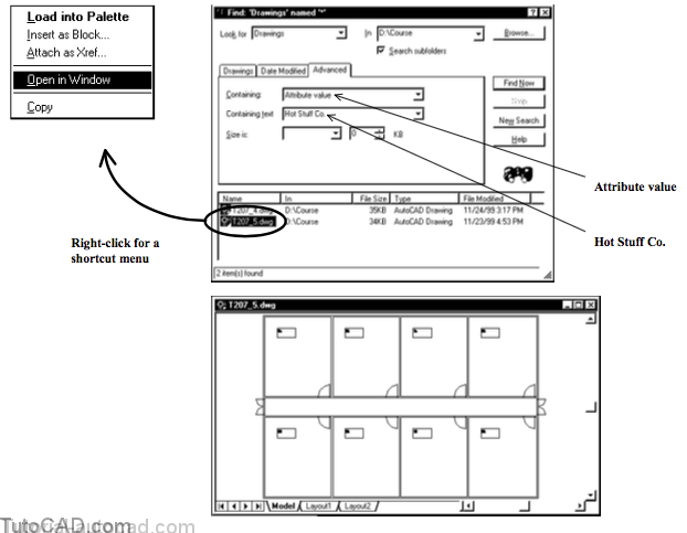
DesignCenter is a powerful tool for finding drawings to Open and if you use attributes you have even more control in your searches.
» 6) Close the Find Window.
» 7) Pick Tools + AutoCAD DesignCenter to close this tool (if desired).
» 8) Close the drawing that you found using DesignCenter.
More Practice
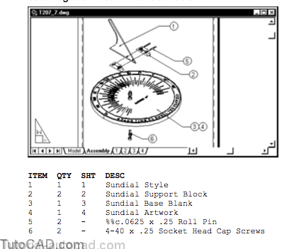
Attributes are commonly used to generate simple bills of materials in assembly drawings.
- in this exercise you will define your own balloon block that will contain 4 different attributes (only one of them is visible).
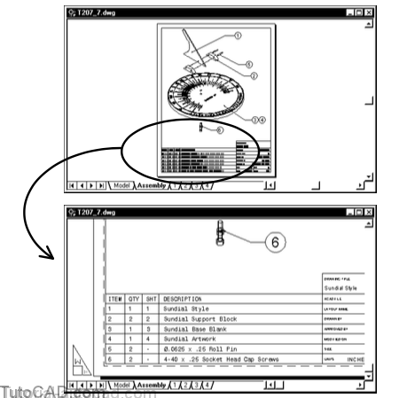
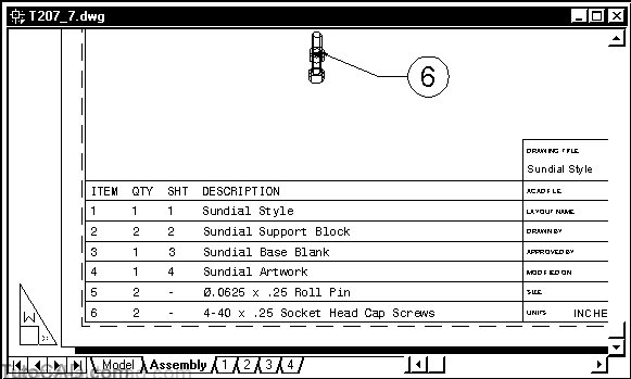
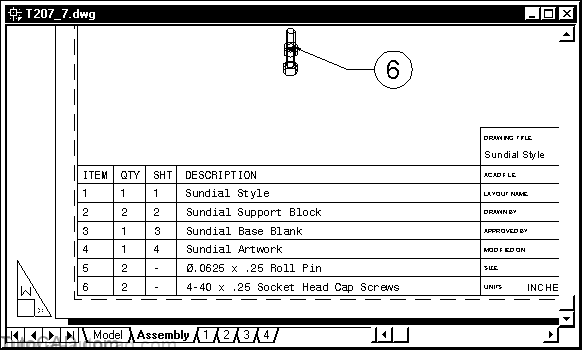
- you will use the Qleader command to insert the balloon block with a leader and the completed Plot Preview is shown below.
- an enlarged view of the completed bill of materials is also shown.
An appropriate template file has already been created for this exercise but you can create your own if you prefer.
PRACTICE USINE ATTRIBUTES TO AUTOMATICALLY CREATE A BILL OF MATERIALS
»1) Close all drawings from previous exercises.
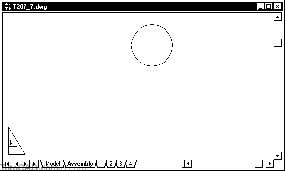
»2) Open the T207_7.dwg drawing in your personal folder.
»3) Pick Draw + Circle + Center,Diameter. Pick any point near P1 as the center point and enter 0.5 as the diameter.

You created a CIRCLE that you will use in a new block for making a detail balloon.
- you are in paper space so the size of this balloon is the size that you want the balloon to be when you Plot.
- you could use this block for drawings in any scale.
» 4) Zoom in to this new CIRCLE so that your screen resembles the following illustration.
5) Pick Draw + Block + Define Attributes. Type ITEM as the Tag, Item number as the Prompt and 1 as the Value. Change Justification to Middle, Text Style to NOTES and the Height to 0.25. None of the Mode boxes should be checked. Pick the Pick Point button to continue.
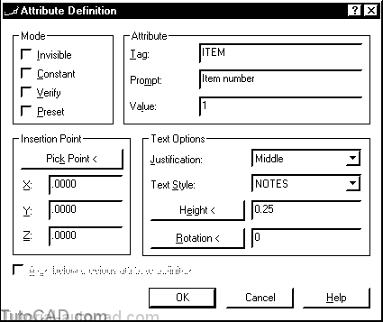
6) Use a Center osnap for the Insertion Point and then pick OK to create the new ATTRIBUTE DEFINITION.

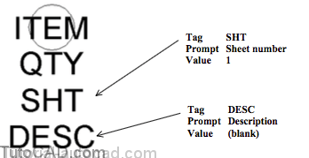
7) Right-click in the drawing to invoke a shortcut and select Repeat Define Attributes. Then check Invisible and check Align below previous attribute definition. Type QTY as the Tag, Quantity as the Prompt and 1 as the Value then pick OK to create another attribute definition.
8) Use a similar technique to create 2 more invisible attribute definitions with the parameters shown below.
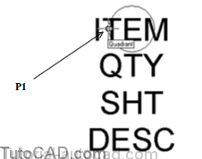
9) Pick Draw + Block + Make. Type B as the Name and enter Detail balloon with attributes as the Description. Then pick the Pick point button to continue.

10) Press & hold <Shift> while you right-click in the drawing area to invoke a shortcut. Select Quadrant and left-click near P1 when you see the Quadrant osnap tooltip to use this as the base point.
11) Pick the Select Objects button then select the CIRCLE and each of the ATTRIBUTE DEFINITIONs in the same sequence that you created them & press <enter> to return and pick OK to create the new block definition.
You will be using the Qleader command to draw leaders with your balloon block at the end (instead of the normal MTEXT object).
- in the next few steps you will change the Settings for Qleader so this happens automatically in this drawing.
» 12) Zoom out until your display resembles the illustration below.
» 13) Pick Dimension + Leader. Right-click in the drawing area to invoke a shortcut and pick Settings. Select Block Reference as the Annotation in the Annotation tab. & pick OK to continue.
Command: QLEADER ↵
Specify first leader point, or [Settings]<Settings>: (right-click & select Settings)

14) Pick near P1 as the start point then near P2. Turn On the POLAR tool in the status bar (if it is Off) and pick near P3 for the final point of the leader. Enter B as the block name and enter @ to use the last point as the insertion point. Press <enter> three times to continue.
Specify first leader point, or [Settings]<Settings>: (pick near P1) Specify next point: (pick near P2)
Specify next point: (pick near P3 with POLAR On)
Enter block name or [?]: B↵
Specify insertion point or [Scale/X/Y/Z/Rotate/PScale/PX/PY/PZ/PRotate]: @↵
Enter X scale factor, specify opposite corner, or [Corner/XYZ] <1>: ↵
Enter Y scale factor <use X scale factor>: ↵
Specify rotation angle <0>: ↵

15) Type Sundial Style as the Description and pick OK to use the defaults for the other attributes.

16) Zoom out and use a similar technique to create the remaining 5 balloons as shown with the attribute values for each tag identified in the table below.
Do NOT use Qleader to create balloon number 4
- simply Copy the B block for number 3 using Quadrant osnaps.
- then edit the attribute values for number 4 using Attedit.
17) Type ATTEXT. Select Space Delimited File (SDF). Pick the Template File button and select T207_bom.txt in your personal folder and pick Open to return. Pick the Output File button and type BOM in your personal folder and pick Save to return. Pick the Select Objects button and pick each B block in the proper sequence and press <enter> to continue. Then pick OK to generate the output file.

You just created a text file that you can now use to automatically generate an accurate bill of materials back in the drawing.
- but first you will create a grid of LINEs that you can overlay the MTEXT for the bill of materials.
- you will draw LINEs that align with existing LINEs in the title block insert on this layout.
» 18) Zoom into the lower part of the title block and create 7 LINEs across the sheet that align with the existing LINEs in the title block.
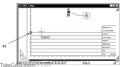
» 19) Pick Draw + Text + Multiline Text. Invoke the Endpoint osnap near P1 and left-click to use this as the start point. Enter S to invoke Style and enter MONO as the style name. Enter W to invoke Width and enter 0 as the new width.
Command: MTEXT ↵
Current text style: “NOTES” Text height: .2500
Specify first corner: (pick near P1 with an Endpoint osnap)
Specify opposite corner or [Height/Justify/Line spacing/Rotation/Style/Width]: S ↵
Enter style name or [?] <NOTES>: MONO ↵
Specify opposite corner or [Height/Justify/Line spacing/Rotation/Style/Width]: W ↵
Specify width: 0 ↵
20) Change the text height to 0.1000 & pick the Line Spacing tab to continue.

21) Select Exactly as the Line spacing and type 0.25 in the adjacent box as the space to use. Left-click in the Mtext editor then pick the Import Text button. Select the BOM.txt file in your personal folder and pick Open to return. Insert your cursor at the top of the imported text and press <enter> to create a blank line at the top. Insert your cursor in this top line and type the headings for each column as ITEM QTY SHT DESCRIPTION (adding appropriate spaces so they line up with the columns). Pick OK to create this MTEXT.

Each MTEXT line begins directly under the LINE object above it which is not easy to read in the drawing.
- the text height is 0.1 and the space between lines is 0.25
- if you Move the MTEXT object down and to the right by 0.075 in each direction, each MTEXT line will be centered in the grid.
22) Pick Modify + Move and enter L to select the Last (MTEXT) object. Type 0.075, –0.075 as the displacement and press <enter> at the prompt for the second point to add some space around each line of text.
23) Use Line to draw vertical column LINEs with appropriate osnaps to complete your drawing.
24) Save your work and Close the drawing.