Generating Isometric Views for a 3D drawing
When you use SOLID models to generate 2D drawings you can easily add an isometric view with hidden lines removed.
- this will make it easier to visualize your parts compared to drawings that include only orthographic views.
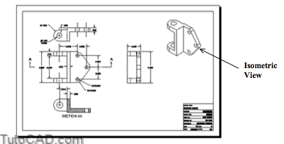
You can create a viewport that shows the SOLID from an isometric viewing direction (e.g. SE Isometric)
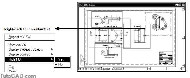
- then set up the viewport so that it will always Plot with hidden lines automatically removed.
- select the viewport with no command running and right-click in the drawing to invoke a shortcut.
- then pick Hide Plot and select Yes.
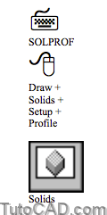
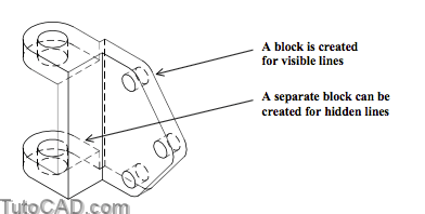
You can also use the Solprof command to create an isometric view of your SOLID models.
- one advantage of this approach (compared to using Hide Plot) is the option to create separate profiles for visible & hidden lines.
- you can assign HIDDEN linetypes to the hidden lines layer or turn that layer off if desired.
You must be in a Layout and a viewport must be active (i.e. you must see MODEL displayed in the status bar) to use Solprof.
- you are prompted to select SOLIDs and you can select one or more SOLIDs to generate a profile.
Command: SOLPROF↵
Select objects: (pick SOLID)
Select objects: ↵
Display hidden profile lines on separate layer? [Yes/No] <Y>: ↵
Project profile lines onto a plane? [Yes/No] <Y>: ↵
Delete tangential edges? [Yes/No] <Y>: ↵
One solid selected.
Command:
Solprof Layers
The layer name for visible lines begins with the letters PV
- and the layer name for hidden lines begins with the letters PH (if you choose to place hidden lines on a separate layer).
- a unique suffice is appended to these letters (based on the viewport handle) to ensure unique layers are created.
- for example, the layer names would be PV-45A and PH-45A if the handle for the viewport was 45A.
These layers are frozen in new viewports by default
- and Solprof will also freeze these new layers automatically in existing viewports so you only see them in the original viewport.
Project to a plane
If you choose to project profile lines to a plane (the default) 2D objects are projected to a plane parallel to the current view.
- otherwise 3D objects are used to represent the edges and silhouette profiles of the selected SOLID.
- if you plan to export the view to a true (flat) 2D drawing later on you should use the default option.
Tangential edges
Isometric views will be cleaner when you delete tangential edges (the default) but you have the option to keep them if required.

You must make a new viewport with Vports (whether you use Solprof or the Hide Plot approach) to create an isometric view.
- the VPORTS layer should be current before you create the new viewport (so the viewport border does not Plot).
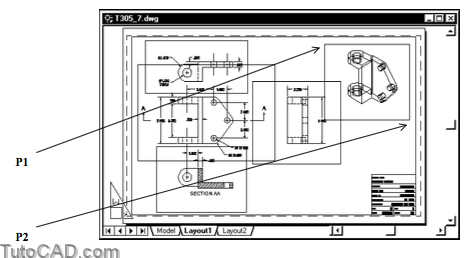
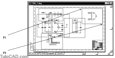
- pick two opposite corners (P1 & P2) for the desired viewport.
PRACTICE GENERATING ISOMETRIC VIEWS
»1) Open the T305_7.dwg file in your personal folder (or use the drawing you created in the last exercise).
»2) Make VPORTS the current Layer.
»3) Make sure OSNAP is Off in the status bar.
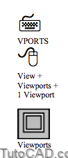
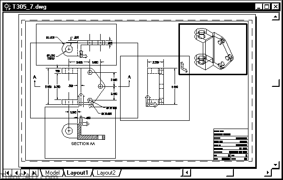
»4) Pick View + Viewports + 1 Viewport. Pick near P1 and P2 by eye to create a new viewport.
5) Double-click inside this viewport to make it the active viewport and switch to the MODEL.
6) Pick View + 3D Views + SE Isometric.
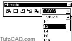
7) Right-click on any toolbar to invoke a shortcut and select Viewports (if it does not already have a check beside it).
8) Select 1:2 as the drawing scale and then dismiss the Viewports toolbar (if you wish).
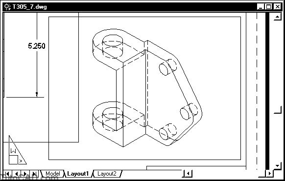
9) You may have to invoke Pan to center the SOLID in this new viewport at this 1:2 scale as shown below.
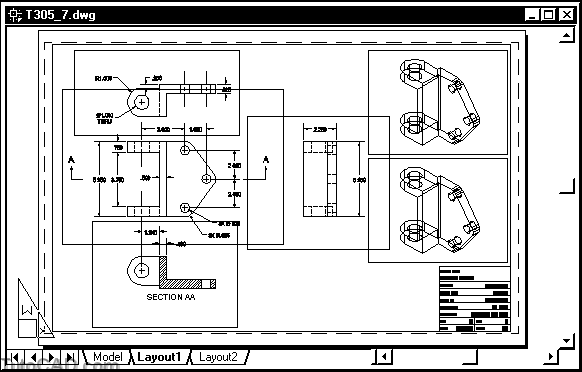
10) Double-click on the PAPER (at any point outside viewports) to switch back out to paperspace.
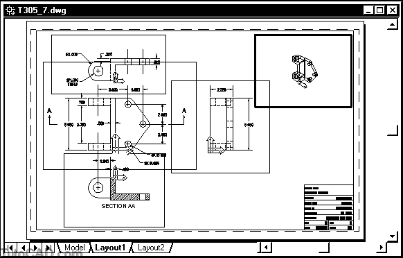
11) Pick Modify + Copy. Select the new VIEWPORT and press <enter> to continue. Then pick two points by eye to create a new identical viewport below the first viewport as shown.
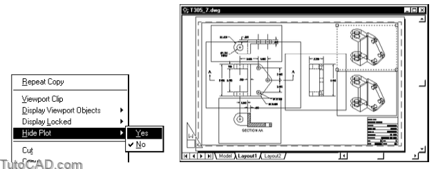
12) Select the top viewport when no command is running to highlight the border. Right-click in the drawing area to invoke a shortcut and pick Hide Plot then select Yes.
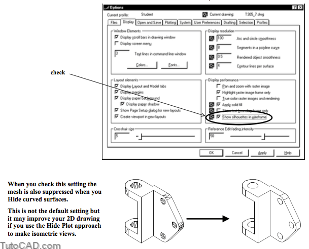
13) Pick Tools + Options. On the Display tab check Show silhouettes in wireframe. Then pick OK.
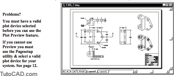
14) Pick File + Plot Preview. Then press <esc> to exit.
The top viewport would Plot with hidden lines automatically removed because Hide Plot was set to Yes for this viewport.
- the viewport below displays and plots the SOLID object the same way without removing hidden lines.
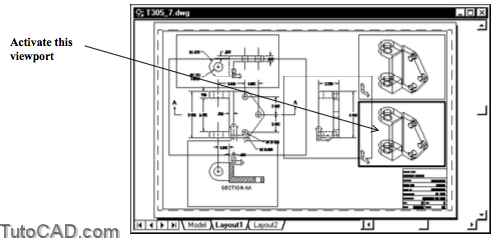
» 15) Double-click inside the bottom viewport to activate it.
16) Pick Draw + Solids + Setup + Profile & use the command line history below as a guide to generate a profile.
Command: SOLPROF↵
Select objects: (pick the SOLID intheactive viewport)
Select objects: ↵
Display hidden profile lines on separate layer? [Yes/No] <Y>: ↵
Project profile lines onto a plane? [Yes/No] <Y>: ↵
Delete tangential edges? [Yes/No] <Y>: ↵
One solid selected.
Command:
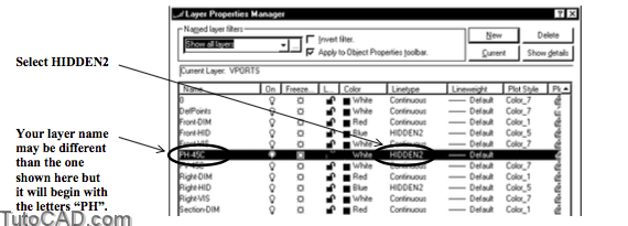
17) Pick Format + Layer. Locate the layer with a name that begins with PH (Profile Hidden) and change the Linetype to HIDDEN2 for this layer.
18) Select the Solid layer and scroll over (if required) to see the layer setting for the Active viewport. Left-click on the icon in this column to Freeze the Solid layer in the current (active) viewport. Then pick OK.
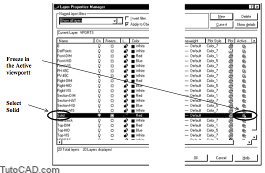
Unlike Soldraw, you must manually Freeze the Solid layer in the active viewport after you use Solprof.
- otherwise, the SOLID object is superimposed on the profile.
» 19) Left-click on the MODEL status bar button to switch back out to the PAPER.
» 20) Pick View + Zoom + Window to zoom into the view with the generated profile.
21) Save the changes to your drawing and Close the file.