How to use Lineweights (Introduction)
Here is a free lesson how to use Lineweights in AutoCAD
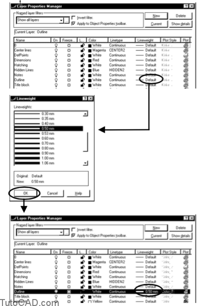
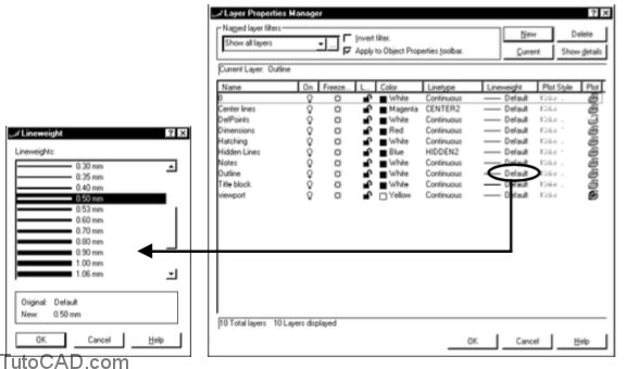
Use the Layer dialogue box to assign lineweights BYLAYER.
- left-click on the lineweight assigned to the desired layer.
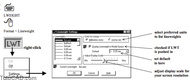
- select one of 28 available lineweights (specified in either millimeters or inches) from the Lineweight dialogue box.
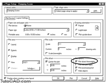
Lineweights will Plot if you check Plot with lineweights on the Layout Settings of the Page Setup dialogue box.
– this box is automatically checked (read-only) when Plot with plot styles is checked.
Lineweight On-screen
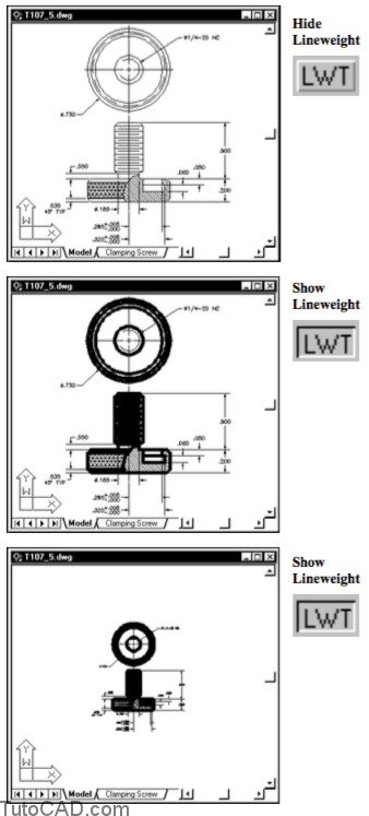
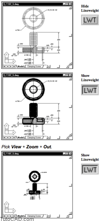
- Left-click on the Show/Hide Lineweights status bar button to toggle the display of lineweights on-screen.
- this setting has no effect on lineweights when you Plot.
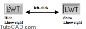
Right-click on the LWT status bar button to invoke a shortcut menu & select Settings to invoke the Lweight command.
Lineweight display on the Model tab
Lineweight is relative to the screen size (i.e. number of pixels) when you display lineweights on the Model tab
- so when you Zoom Out the apparent lineweight (relative to objects) increases to impractical widths.
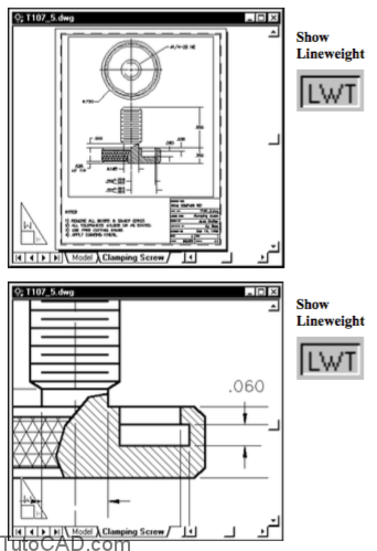
Lineweight display on Layout tabs
Lineweights displayed on Layouts are close to the true lineweights that you will get in Plots (relative to objects).
- Zoom out and lineweights decrease in apparent size.
- Zoom in and lineweights increase in apparent size.
Hide Lineweights and use the plot Preview feature to verify that lineweights are set to your preferences instead.
![]()
– your system performance may improve by not displaying lineweights on-screen as well.
– remember that lineweights will Plot if you check Plot with lineweights in the Page Setup dialogue box.
practice assigning lineweight BYLAYER
- Close the drawing from the previous exercise (if it is open).
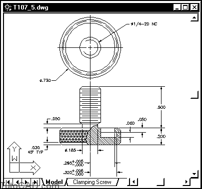
- Open the T107_5.dwg drawing in your personal folder.
In this drawing all layers are assigned the Default lineweight.
In this exercise you will assign a lineweight of 0.50mm to the Outline layer.
- Invoke the Layer command. Left-click on the Default lineweight that is currently assigned to the Outline layer to invoke the Lineweight dialogue box. Scroll down the list to select 0.50mm and pick OK to return to the Layer dialogue box. Then pick OK to complete the Layer command.
- Left-click on the LWT status bar button a few times to toggle it On & Off. Stop when LWT is On.
- Right-click on the LWT status bar button to invoke a shortcut and select Settings. Then slide the Adjust Display Scale slider to Min and pick OK to complete the change.
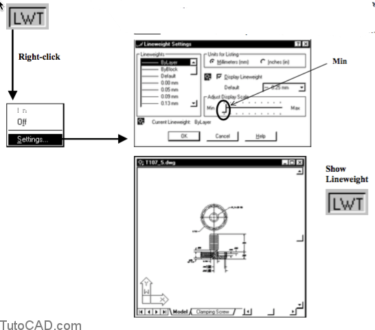
Lineweights now appear as though LWT is Off even though it should be On right now.
– lineweight is arbitrarily scaled when displayed on the Model tab. – if you work & Plot on the Model tab you should leave LWT Off as this is not useful information.
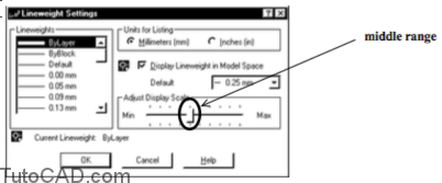
- Return Adjust Display Scale to a middle range value.
- Left-click on the Clamping Screw layout tab to make this the current tab.
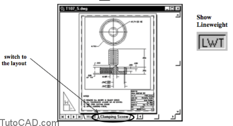
- Zoom into a closer view (similar to the one shown below) to see how lineweights are displayed on a layout tab.
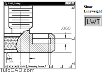
Objects on the Outline layer display with a heavier lineweight because you assigned the 0.50mm lineweight to this layer.
– objects on other layers (Hatching & Dimensions) use a lighter lineweight as the Default lineweight is still assigned to them.
– the Default linetype is normally 0.15mm but you can change this using the Lweight command.
- Save the changes to T107_5.dwg then Close this file.