Key Settings For New Dimension Styles
The changes you make in custom dimension styles will depend on the type of drawings that you want to create.
- some settings may be dictated by accepted drafting standards.
- other settings may be dictated in office standards established by the company that you work for.
- each drawing unit (i.e. mm vs inches) has unique requirements.
There are so many different settings to consider that an attempt to review all of them could be counter-productive.
- this section addresses some of the more important settings that you are likely to change for common applications.
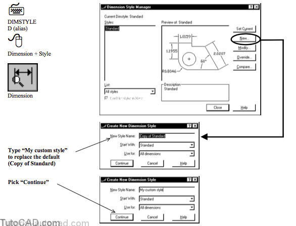
Defining new dimension styles
You define new dimension styles in the active drawing with Dimstyle (Dimension Style Manager) by picking the New button in this box.
- enter a new style name then select an existing style (e.g. Standard) to start with.
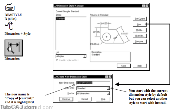
You normally type a name of your choice for the new style but if you do not type a new name it will remain as “Copy of [start with name]”.
You should leave Use for set to All dimensions unless you want to explicitly create a sub style for specific dimension types.
- you will learn more about sub styles later in this document.
When you pick Continue you are prompted to modify dimension variable settings and these settings are arranged on logical tabs.
- there are 6 different tabs to choose from.
Settings are also arranged logically on each tab with reasonable descriptions beside them
- when you change settings you will see the impact of the change in the preview pane.

You can experiment with dimension settings without having to know very much about a particular setting before hand.
- if your changes lead to unexpected results in the preview simply pick Cancel to avoid making any changes.
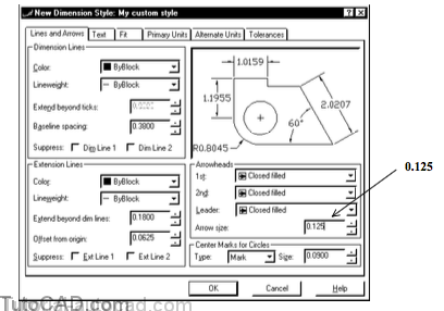
Lines & Arrows
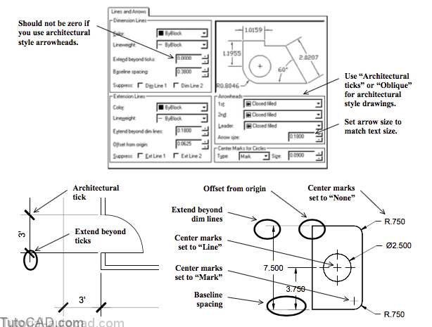
Mechanical drawings normally use a Closed filled arrowhead
- whereas architectural drawings normally use an Architecturaltick or Oblique arrowhead
- and you can change Extend beyond ticks to a non-zero value (e.g. equal Arrow size) if you use architectural style arrowheads.
Arrow size is normally set to match the value used for Text height (the size that you would want to measure in an actual plot).
Baseline spacing sets the space between dimensions when you use the Dimbaseline command (set this before making dimensions).
The Extension beyond dim lines distance controls how far the extension lines extend beyond the dimension lines.
The Offset from origin distance controls how close the extension lines get to the dimension origin points.
Center Marks for Circles can be either Mark, Line or None and this affects radial & diameter dimensions for CIRCLEs & ARCs.
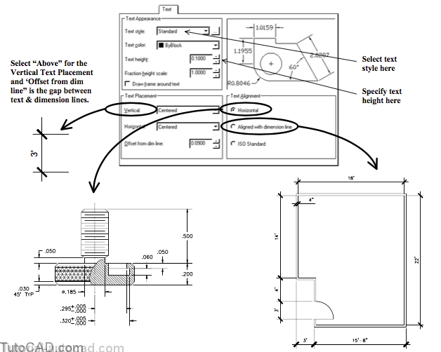
Standard & ISO-25 dimension styles use the Standard text style for dimension text (it does not matter which text style is current).
- the Standard text style uses a TXT.shx font which was designed to display & Plot with maximum speed (not to look good).
- you can use Style to define a text style with an attractive font (e.g. Arial) then select this text style for the dimension style.
- use a standard font that is likely to be installed on other computers if you plan to distribute your drawings to others.
You should use a value for text height according to the height of text that you would want to measure in an actual plot.
(Vertical) Text Placement controls whether the dimension text is Above or Centered (inserted in) dimension lines.
Text Alignment controls whether dimension text is Horizontal or Aligned with dimension line.
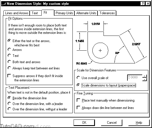
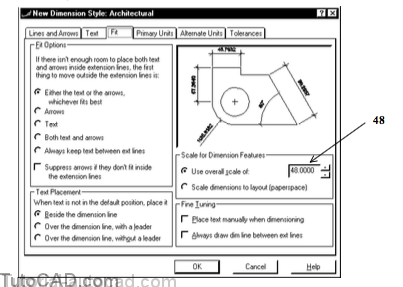
The most important setting on the Fit tab is the Scale for Dimension Features (the descriptions for other settings are relatively intuitive).
- this controls the size of dimension features (e.g. text height, arrow size, etc..) when you Plot.
- this does NOT change dimension text values (e.g. distance).
If you Plot drawings from a Layout tab (paperspace) the simplest approach is to select Scale dimensions to layout (paperspace)
- then as you create new dimensions (or update existing dimensions) they are automatically scaled for your drawing scale.
- you must create the dimensions in the model when you are on the layout (you should see the word MODEL in the status bar)
- the viewport should be zoomed to the desired drawing scale (that you plan to Plot with) before creating/updating dimensions.
If you Plot your drawings from the Model tab you should select Use overall scale of and then type an appropriate value in the edit box.
- when you express the drawing scale as A:B (e.g. 1:10) you could calculate an appropriate scale factor as B A (e.g. 10).
In either case (plot from Model or Layout tab) you should set all size related variables (e.g. text height) to the values you want in the Plot.
- then AutoCAD will automatically scale dimension object features so that they appear the correct size when you Plot.

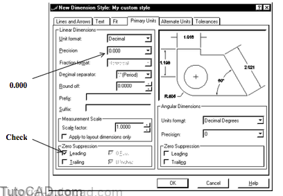
Primary Units
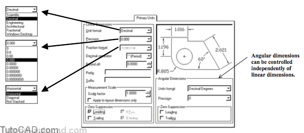
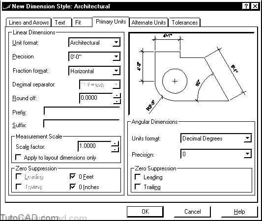
The Unit format lets you select a format for dimensions from a similar set of options available in the Units command.
- however, this dimension variable setting is independent of the setting that is changed with the Units command.
- you can also specify Angular units format on this tab.
– The Precision setting controls the number of decimal places and you can control Angular & Linear precision independently.
– Fraction format controls how fractions are displayed in dimensions (available only for Architectural & Fractional Unit formats).
– The Decimal separator lets you use any character before decimals (e.g. some countries use a comma instead of the default period ).
– AutoCAD will automatically round off dimension values to the specified Round off value.
– You can automatically merge any Prefix or Suffix text with the measured dimension text.
– The measurement Scale factor lets you multiply measured dimension values by a scale factor.
- for example, you could enlarge objects by a factor of 5 in a detail view & dimension the objects with a factor of 0.2 to compensate.
Zero suppression controls weather or not zeros are displayed before and after decimals and this setting is dictated by drafting standards.
- for example, ANSI standards for drawings in inches specify that leading zeros should be suppressed (e.g. 0.500 should be .500).
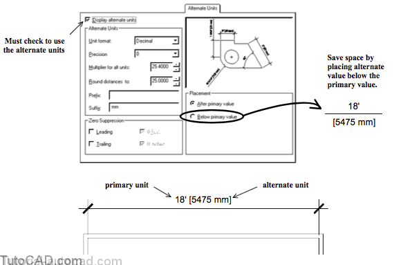
Alternate Units
The Alternate Units tab lets you set up a dimension style that can display dimension text for two different units at the same time.
- for example, you could create a drawing in inches and set up the primary units for the architectural (feet & inches) units format.
- you could then set up alternate units to scale decimal dimension values appropriately for the equivalent mm values.
- the alternate units are displayed inside square brackets if you check Display alternate units on this tab.
- you can even Round distances to a specified value.
The Multiplier for alt units is the number that you must multiply a primary units value by to arrive at the alternate units value.
- for example, there are 25.4 mm per inch so the multiplier would be 25.4 if primary units are inches & alternate units are mm.
When you use alternate units it is practical to include the alternate unit description (e.g. mm) as a Suffix
- you may also want to include a space before the suffix text.
You might save space by selecting Below primary value for the Placement (instead of the default After Primary value).
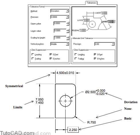
Tolerance
The Tolerance tab lets you control the Method to display tolerances and you can specify the Upper value & Lower value to use.
- when you use the Limits method the Upper value is added and the Lower value subtracted from the measured value.
- use the Deviation method to display the Upper value & Lower value beside the measured value.
- use the Symmetrical method to save space when the Upper value & Lower value are the same.
- the Basic method draws a box around the measured value (normally found in drawings that use Geometric Tolerances).
Use the Scaling for height to create tolerances with a different text height compared to other dimension text.
The Vertical position controls the vertical justification of tolerances.
Tolerances have their own settings for Zero Suppression & Precision that can also be different for Alternate Units.
If you work with Geometric Tolerances you can create special feature control frames that conform to ANSI & ISO standards.
- these special objects are generated using the Tolerance command (they are NOT generated through dimension styles).
- use AutoCAD Help for the Tolerance command to learn more about this utility.
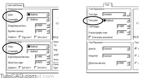
Color and Lineweight
You can create objects using the current color & lineweight and one (efficient) way to set these object properties is ByLayer.
- you can also control object lineweight in plots by the width of the pens that you use (configure for) in your plotter.
You can plot objects with different pens in a plotter according to the object color as it appears on the screen in AutoCAD.
- this method of lineweight control uses the Color dependent plot style behavior & it was the only option prior to AutoCAD 2000.
- you can also explicitly assign lineweight to objects (or layers) or use Named plot style behavior to override properties in plots.
You can change the color & lineweight for Dimension Lines, Extension Lines & Text (color only) on appropriate Dimstyle tabs.
- if Color & Lineweight are ByBlock (default) the current settings for Color & Lineweight (normally set ByLayer) are used.
There are many different methods to arrive at the desired results for lineweight but you should standardize on ONLY ONE METHOD.
- otherwise, it may be very confusing.
PRACTICE CREATING NEW DIMENSION STYLES
1) Close the drawings from the previous exercise.
2) Open the T205_3.dwg drawing in your personal folder.

3) Pick Dimension + Style. Pick New and type My custom style to replace the default name & pick Continue.
4) Select the Lines and Arrows tab and change the Arrow size from 0.1800 to 0.125. Pick the Text tab to continue.
5) Pick the button to invoke the text Style command.
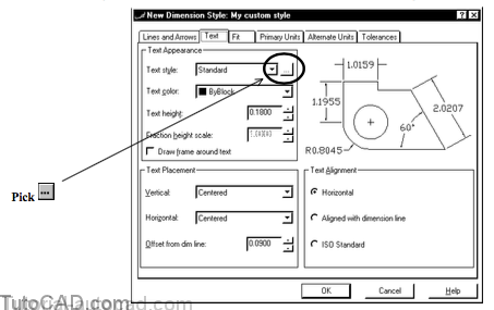
This dimension style uses the Standard text style right now and this is not a very attractive style to use for dimension text.
- you will define a new text style called My dimensions in the next step and this style will use the Arial font.
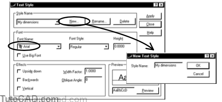
You can use the Style command to define new text styles
- or you can invoke this command transparently when you are running the Dimstyle command (as in this example).
6) Pick the New button & type My dimensions as the new text style name & pick OK to return to the Text Style box. Select Arial as the Font Name and pick Apply. Then pick Close to return to the Text tab in the Dimension Style Manager.
7) Select the new My dimensions text style and enter 0.125 as the Text height. Then pick the Fit tab to continue.
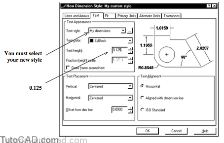
The My dimensions text style is the current style.
- if you create new TEXT objects (e.g. using Dtext) this TEXT would automatically use the My dimensions text style.
You must explicitly select the new text style when you define a new dimension style
- the current text style is NOT automatically used by the current dimension style.
8) Select Scale dimensions to layout (paperspace) and pick the Primary Units tab to continue.
9) Select 0.000 as the Precision and check Leading Zero Suppression for Linear Dimensions. Pick OK to return to the main box (but do not terminate the Dimstyle command yet).
When you create New dimension styles they do NOT become the current style automatically.
- you must explicitly make a new dimension style current.
10) With My custom style selected in the Styles list, pick the Set Current button. Then pick Close.
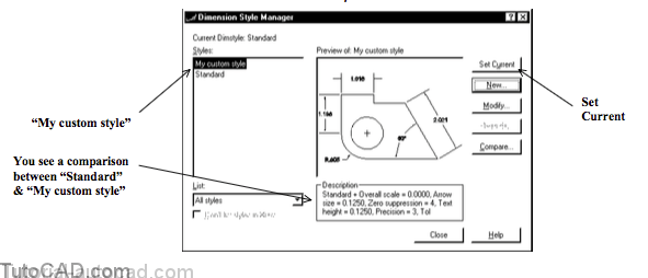
You can compare two dimension styles by selecting the desired style and picking the Compare button.
- you are prompted to select another style to compare the selected style with.
- by default you also see some of the differences between the current style and the selected style in the Description area.
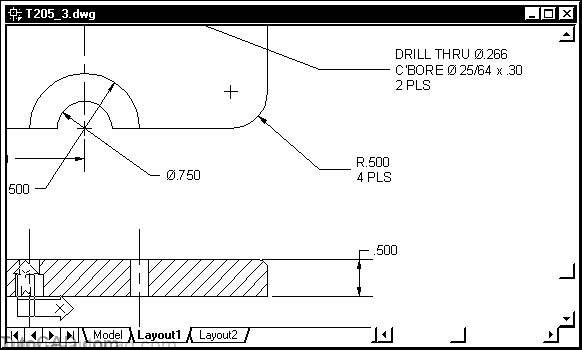
» 11) Pick Dimension + Update. Enter ALL and press <enter> to apply the new current dimension style to all dimensions.
» 12) Zoom In for a closer view of some dimensions to verify that the dimensions now use the new settings.
More practice?
13) Save the changes to the current drawing & Close the file.
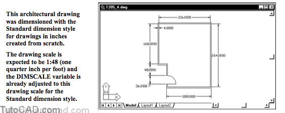
14) Open the T205_4.dwg drawing in your personal folder
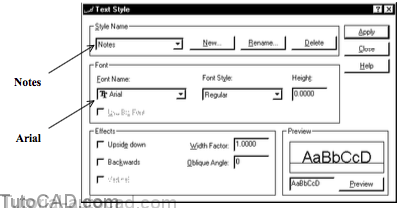
15) Pick Format + Text Style. Pick New and enter Notes as the new style name. Pick OK to return and select Arial as the Font Name. Pick Apply then pick Close.
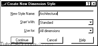
16) Pick Dimension + Style. Pick the New button there and enter Architectural as the new name then pick Continue.
17) Select the Lines and Arrows tab. Select Architectural tick for 1st & 2nd Arrowheads. Then enter 0.125 for Extend beyond ticks , Extend beyond dim lines & Arrow size. Pick the Text tab to continue.

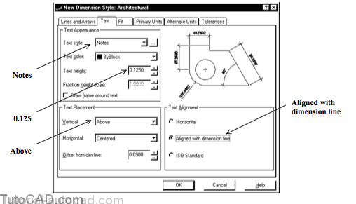
18) Select Notes as the Text style. Enter 0.125 as Text height. Select Above for Vertical Text Placement. Select Aligned with dimension line for Text Alignment. Then pick the Fit tab to continue.
The Standard dimension style was already adjusted to Plot from the Model tab for a drawing scale of 1:48
19) Verify that Use overall scale of is set to 48. Then pick the Primary Units tab to continue.
20) Select Architectural for Unit format and select 0’-0” as the Precision. Then pick OK to return to the main box.
21) Select Architectural as the dimension style and pick the Set Current button to make this the current style. Then pick Close to terminate Dimstyle.

22) Pick Dimension + Update. Enter ALL then press <enter> to update all dimensions to the new Architectural style.

In relatively few steps you created a reasonable dimension style to use for architectural drawings in inches.
- you may want to Zoom In for a closer look at some of these dimensions.
23) Save the changes to this drawing & Close the file.