Setting Up Viewports With SOLVIEW in a 3D drawing
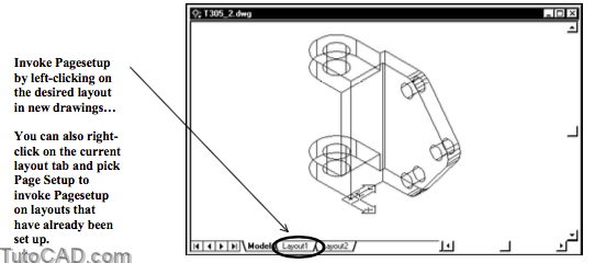
Your first task (before setting up viewports on a Layout) should be to set up the desired Layout for your 2D drawing using Pagesetup.
- you can refine the setup with Pagesetup later on but you should (at least) initially select the desired plot device & sheet size.

If you have not already set up a layout you will invoke Pagesetup automatically by left-clicking on a layout tab
- you can also invoke Pagesetup in a shortcut by making a layout current, right-clicking on the layout tab & picking Page Setup.
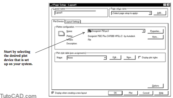
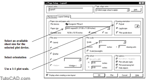
When you have selected the desired plot device you can specify the sheet size on the Layout Settings tab.
- you will also normally select 1:1 for the plot scale even if your drawing scale (view magnifications) are not 1:1.
- orientation (e.g. Landscape) should be set at this stage as well.
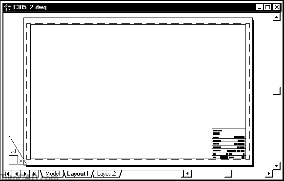
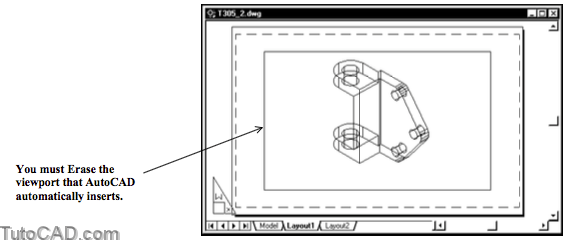
AutoCAD will automatically create an arbitrary viewport by default.
- you will want to Erase this viewport (created on the current layer) before using Solview.
- remember that Soldraw can only generate drawings automatically in viewports that are created by Solview.

While it is not a requirement at this point you will probably want to Insert your custom title block into the Layout before using Solview.
- then you will know how much space is available for the new viewports that you are about to create.
You can use Pagesetup again to select Extents as the Plot area (now that there is an object on the Layout) & check Center the Plot
- then the title block will be centered on the page when you Plot
- so you will avoid clipping parts of the title block if the title block actually fits in the printable area for the selected plot device.

You should make the XY plane of current UCS parallel to the first view in your 2D drawing layout before using Solview.
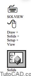
You can invoke Solview from the Layout tab or from the Model tab but you will automatically switch to the Layout tab.
- one way to begin a new layout is to use the Ucs option.
- you are prompted for a view scale, view center, corner points of the desired viewport and a view name.
Command: SOLVIEW↵
Enter an option [Ucs/Ortho/Auxiliary/Section]: U↵
Enter an option [Named/World/?/Current] <Current>: ↵
Enter view scale <1.0000>: 0.5 ↵
Specify view center: (pick near P1)
Specify view center <specify viewport>: ↵
Specify first corner of viewport: (pick near P2)
Specify opposite corner of viewport: (pick near P3)
Enter view name: Front ↵
UCSVIEW = 1 UCS will be saved with view
Enter an option [Ucs/Ortho/Auxiliary/Section]: ↵
Command:
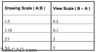
View Scale
The view scale is the drawing scale for the new viewport.
- for example, if the desired drawing scale is 1:2 (1 plotted unit equals 2 drawing units) you could use a view scale of 0.5.
- when you express drawing scale as A:B the view scale can be
calculated as B +A (see more examples in the table below).
View center
You can keep picking different points for the View center until the SOLID appears in the desired location on your layout.
- the SOLID is temporarily displayed where you pick and you are prompted to pick another point.
- press <enter> to continue (instead of picking another point) when the SOLID is displayed in the desired location.
Viewport corners
You must pick two points for the viewport corners to define the size of the new viewport.
- make viewports large enough to include all dimensions planned for each viewport.
- you can change viewport size later on using grip editing techniques to stretch these corner points.
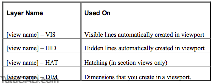
View name
The View name is used to create new layers that will be used by Soldraw when you create 2D geometry for the drawing views.
- the view name is appended by as many as 4 different suffixes for the functions listed in the table below.
Ortho
You can use the Ortho option of Solview to create orthographic views from an existing viewport (that was also created by Solview).
You are prompted to specify the side of a viewport to project.
- pick the (existing) viewport edge on the side closest to the new orthographic view that you want to create.
- steps for creating an orthographic view are the same as for theUcs option after that point.
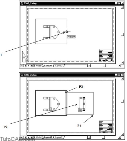
Command: SOLVIEW↵
Enter an option [Ucs/Ortho/Auxiliary/Section]: O↵
Specify side of viewport to project: (pick Midpoint osnap near P1)
Specify view center: (pick near P2)
Specify view center <specify viewport>: ↵
Specify first corner of viewport: (pick near P3)
Specify opposite corner of viewport: (pick near P4)
Enter view name: Right↵
UCSVIEW = 1 UCS will be saved with view
Enter an option [Ucs/Ortho/Auxiliary/Section]: ↵
Command:
You can use the same technique to create all required orthographic views for the entire 2D layout.
Viewports can overlap.
- Solview automatically places viewports on the VPORTS layer and this layer is created automatically if it does not already exist.
- you must manually select the No Plot setting for this layer or viewport borders will appear in plots.

Section Views
- You can use the Section option of Solview to create a viewport for a section of your SOLID.
- you specify a cutting plane in the desired viewport by picking two points & they should be on the XY plane for the best results.
- you must pick a point on the side of this cutting plane to specify the side to view from.
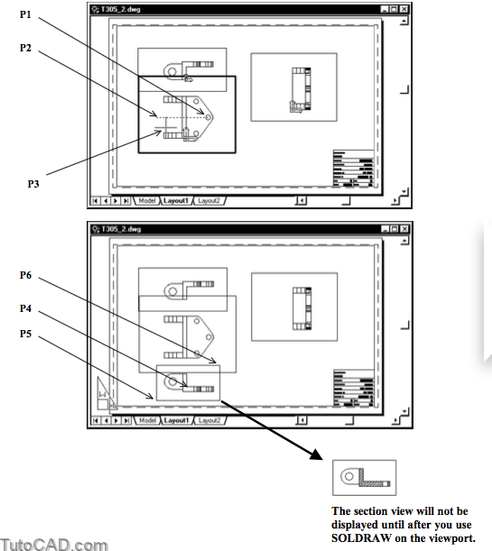
Command: SOLVIEW↵
Enter an option [Ucs/Ortho/Auxiliary/Section]: S↵
Specify first point of cutting plane: (pick P1)
Specify second point of cutting plane: (pick P2)
Specify side to view from: (pick P3)
Enter view scale <.5000>: ↵
Specify view center: (pick P4)
Specify view center <specify viewport>: ↵
Specify first corner of viewport: (pickP5)
Specify opposite corner of viewport: (pick P6)
Enter view name: Section↵
UCSVIEW = 1 UCS will be saved with view
Enter an option [Ucs/Ortho/Auxiliary/Section]: ↵
Command:
Auxiliary Views
Use the Auxiliary option of Solview to create auxiliary views (to display & dimension features at non-orthographic angles).
- the process is similar to the process for creating a section view except you define an inclined plane instead of a cutting plane.
- the inclined plane is defined by two points & you pick a point on the desired side of this plane to specify the viewing direction.
Command: SOLVIEW↵
Enter an option [Ucs/Ortho/Auxiliary/Section]: A↵
Specify first point of inclined plane: (pick near P1)
Specify second point of inclined plane: (pick near P2)
Specify side to view from: (pick near P3)
Specify view center: (pick near P4)
Specify view center <specify viewport>: ↵
Specify first corner of viewport: (pick near P5)
Specify opposite corner of viewport: (pick near P6)
Enter view name: Auxiliary↵
UCSVIEW = 1 UCS will be saved with view
Enter an option [Ucs/Ortho/Auxiliary/Section]: ↵
Command:
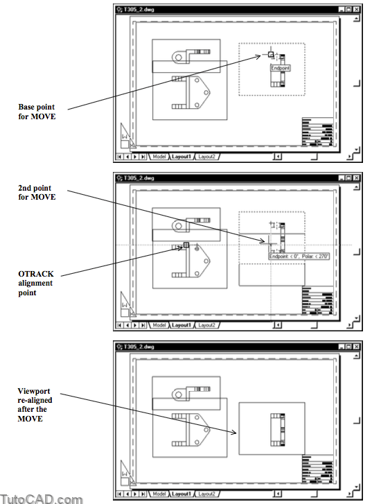
The views in each viewport are initially aligned with one another but this may change if you Move the viewports on the Layout.
- you can precisely re-align viewports with Move using Osnaps when PAPER is displayed in the status bar.
- the OTRACK tool is also practical if you must re-align views.
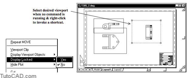
Locking view scale
While it is not necessary, you should lock the viewport scale for all viewports to avoid accidentally changing view scale later on.
- select one viewport (border) with no command running when PAPER is displayed in the status bar.
- right-click in the drawing to invoke a shortcut menu and pick Display Locked then pick Yes.
- then you will automatically switch to PAPER when you use display commands (e.g. Zoom) if MODEL is in the status bar.
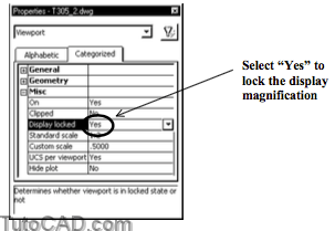
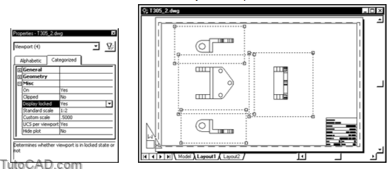
You can also use the Properties command to change this setting for more than one selected VIEWPORT object.
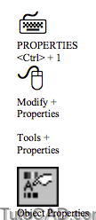
- select Yes for the Display locked property under the Misc Category to lock the display magnification.
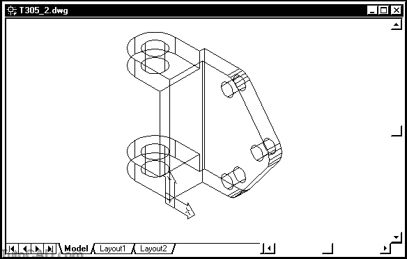
PRACTICE SETTING UP VIEWPORTS WITH SOLVIEW.
» 1)Close the drawing from the previous exercise if it is open.
» 2) Open the T305_2.dwg file in your personal folder.
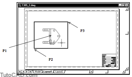
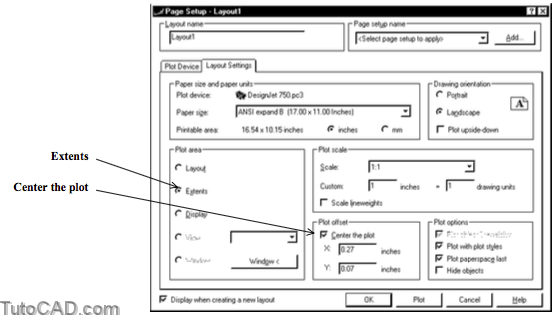
» 3) Left-click on the Layout1 tab to switch to this layout. The Pagesetup utility should be invoked automatically because this layout has not been set up yet. On the Plot Device tab select DesignJet 750.pc3 (or equivalent) as the Name for the Plotter configuration. Then select the Layout Settings tab in Page Setup to continue.

4) Select ANSI expand B (17.00 x 11.00) as the sheet size and verify that the other settings are as shown in the illustration below then pick OK to continue.
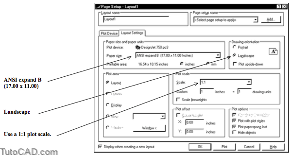
5) Select ANSI expand B (17.00 x 11.00) as the sheet size and verify that the other settings are as shown in the illustration below then pick OK to continue.
Pick Modify + Erase. Select the new VIEWPORT then press <enter> to delete it.
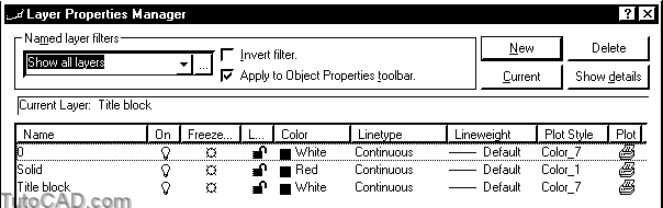
6) Create a New Layer called Title block and make it current.
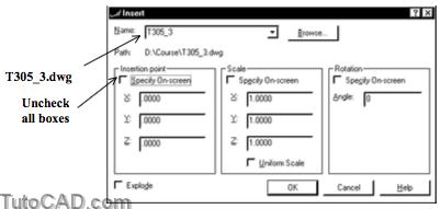
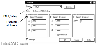
7) Pick Insert + Block. Pick the Browse button and select the T305_3.dwg drawing in your personal folder and pick Open there to return to the Insert dialogue box. Uncheck all Specify On-screen boxes and pick OK to continue.
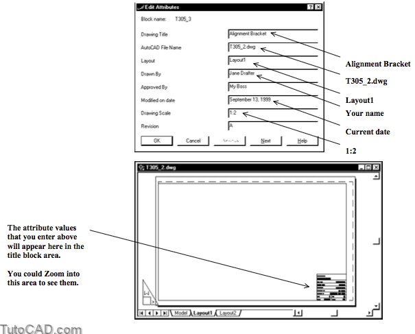
8) You could simply pick OK to leave some of the title block attributes empty or use the values below as a guide.
» 9) Right-click on the Layout1 tab to invoke a shortcut and pick Page Setup.
» 10) Select Extents as the Plot area and check Center the plot. Then pick OK to complete this change.
11) Left-click on the Model tab to return to the Model.
12) Pick Tools + Orthographic UCS + Front to make the FrontUCS the current UCS.

Now you are ready to use Solview to create your first viewport on Layout1 using this Front UCS (to create a Front view).
- you will invoke the Ucs option of Solview and use the current (Front) UCS to specify the viewing direction for the first view.
» 13) Pick Draw + Solids + Setup + View. Enter U to invoke the Ucs option. Follow the command dialogue below to create the first viewport as shown.
Command: SOLVIEW↵
Enter an option [Ucs/Ortho/Auxiliary/Section]: U↵Enter an option [Named/World/?/Current] <Current>: ↵
Enter view scale <1.0000>: 0.5 ↵
Specify view center: (pick near P1)
Specify view center <specify viewport>: ↵
Specify first corner of viewport: (pick near P2) Specify opposite corner of viewport: (pick near P3) Enter view name: Front ↵
UCSVIEW = 1 UCS will be saved with view
Enter an option [Ucs/Ortho/Auxiliary/Section]: ↵
Command:

14) Left-click on the arrow in the Layer control drop-down list and left-click on the printer icon to select No Plot for the VPORTS layer. Left-click on the arrow to roll up the list.
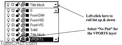
Now when you Plot (or Preview a plot) the borders of viewports created by Solview will not be included.
Solview created 3 new layers for the Front view.
- there are now Front-DIM, Front-HID & Front-VIS layers.
» 15) Pick Draw + Solids + Setup + View again. This time enter O to invoke the Ortho option and follow the dialogue below to create an orthographic view from the right side. Name this new view Right.
Command: SOLVIEW↵
Enter an option [Ucs/Ortho/Auxiliary/Section]: O↵
Specify side of viewport to project: (pick Midpoint osnap near P1)
Specify view center: (pick near P2)
Specify view center <specify viewport>: ↵
Specify first corner of viewport: (pick near P3)
Specify opposite corner of viewport: (pick near P4)
Enter view name: Right↵
UCSVIEW = 1 UCS will be saved with view
Enter an option [Ucs/Ortho/Auxiliary/Section]: ↵
Command:
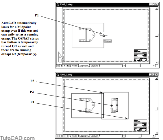
You are NOT prompted for the view scale of this orthographic view.
- AutoCAD automatically uses the same scale as the existing view that you used to project the new view.
- the SOLID displayed in the new viewport is aligned with the SOLID in the original viewport.
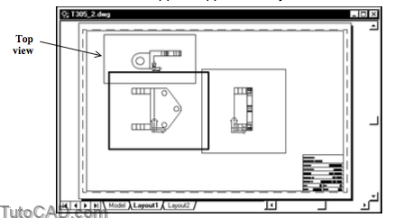
16) Use a similar technique to create another orthographic viewport above the first viewport & name this view Top. Make this view appear approximately as shown below.
17) Pick Draw + Solids + Setup + View. This time enter S to invoke the Section option. Type .XY to invoke a point filter and type CEN to use a Center osnap override. Left-click on the Center osnap marker near P1 as the first point of the cutting plane. Then enter 0 when prompted for a Z value.
Command: SOLVIEW↵
Enter an option [Ucs/Ortho/Auxiliary/Section]: S↵Specify first point of cutting plane: .XY ↵
of CEN↵
of (pickCenterosnapnearP1)
(need Z): 0↵
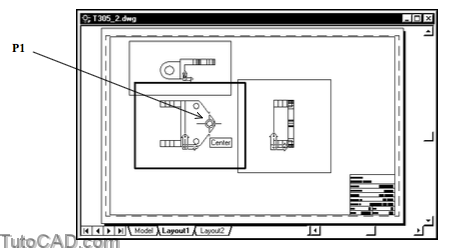
You may get unpredictable results if both points for the cutting plane are not on the XY plane of the current UCS.
- you used a point filter for the first point to make sure that the first point is on the XY plane (the Z ordinate is 0).
18) Left-click on the ORTHO status bar button to turn this tool On. Then pick a point near P1 for the second point of the cutting plane.
Specify second point of cutting plane: <Ortho on> (pick near P1)

19) Pick a point near P2 below this cutting plane line (shown highlighted below) as the side to view from.
Specify side to view from: (pick near P2)

The side to view from determines the viewing direction for the section which should conform to standard orthographic projections.
- you will be placing this new section view below the main viewport
- you just specified the standard orthographic viewing direction for a view located below the main viewport.
20) Press <enter> to use the same view scale <.5000> as the main viewport. Then follow the dialogue below to complete the setup of this new section viewport named Section.
Enter view scale <.5000>: ↵
Specify view center: (pick near P1)
Specify view center <specify viewport>: ↵
Specify first corner of viewport: (pick near P2)
Specify opposite corner of viewport: (pick near P3)
Enter view name: Section↵
UCSVIEW = 1 UCS will be saved with view
Enter an option [Ucs/Ortho/Auxiliary/Section]: ↵
Command:

21) Double-click at any point outside the existing viewports to switch to paper space. You should see the PAPER button in the status bar (instead of MODEL).
22) Select all four VIEWPORT objects. Right-click in the drawing area to invoke a shortcut & pick Properties. Change Display Locked to Yes in the Misc category. Dismiss Properties & press <esc> twice.
23) Save your changes to T305_2.dwg for the next exercise.
24) Close the T305_2.dwg drawing file.
More Practice?
25) Open the T305_4.dwg drawing file in your personal folder.
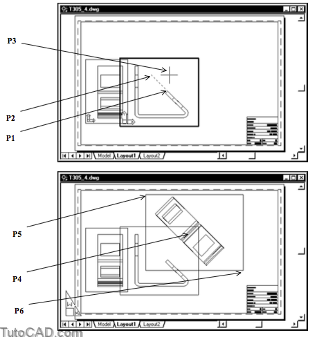
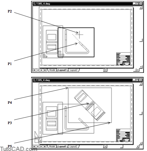
26) Pick Draw + Solids + Setup + View. Enter A to invoke the Auxiliary option. Make the viewport on the right side the current viewport. Follow the dialogue below to create an auxiliary viewport named Auxiliary.
Command: SOLVIEW↵
Enter an option [Ucs/Ortho/Auxiliary/Section]: A↵
Specify first point of inclined plane: ENDP ↵
of (pick Endpoint of LINE near P1)
Specify second point of inclined plane: @2<135 ↵
Specify side to view from: (pick near P2)
Specify view center: (pick near P3)
Specify view center <specify viewport>: ↵
Specify first corner of viewport: (pick near P4)
Specify opposite corner of viewport: (pick near P5)
Enter view name: Auxiliary↵
UCSVIEW = 1 UCS will be saved with view
Enter an option [Ucs/Ortho/Auxiliary/Section]:
Command:
» 27) Save the changes to T305_4.dwg and Close the file.
You have set up several views using Solview.
- at the moment the SOLID object itself appears in each viewport but this will not be acceptable for traditional 2D drawings.
- in the next section you will use Soldraw to generate the drawing views for these viewports.