Tools To Analyze SOLIDs
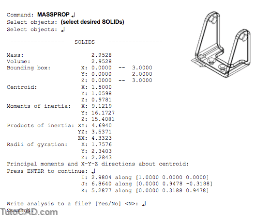
The Massprop command is a quick way to compute basic mass properties of selected SOLIDs relative to the current UCS.

- two common properties are volume (which is equal to the mass because AutoCAD assumes density is 1) & the centroid point.
- you can also compute moments of inertia, products of inertiaand radii of gyration.
- you can read the mass property report on-screen and you also have the option of saving this report to a text file.
- you can use this command on REGIONs for 2D parameters.
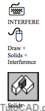
Use Interfere to see if components in an assembly fit together.
- you can select two different sets of SOLIDs to see if any SOLIDs from one set interfere with SOLIDs in the other set
- or you can simply select one set of SOLIDs to see if any of the SOLIDs interfere with other SOLIDs in the same set.
- if AutoCAD discovers any interference you can create a SOLID of interference to help you visualize how these SOLIDs interfere.
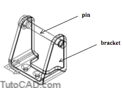
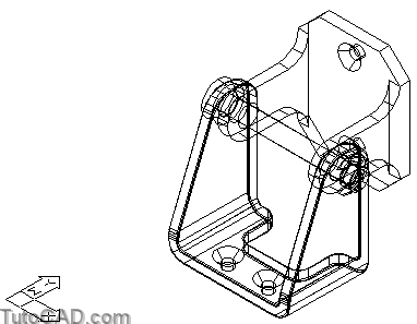
For example, you could compare the pin and bracket SOLIDs shown in the assembly below to see if they interfere with one another.
Command: INTERFERE↵
Select first set of solids:
Select objects: (pick pin)
Select objects: ↵
Select second set of solids: Select objects: (pick bracket)
Select objects: ↵
Comparing 1 solid against 1 solid.
Interfering solids (first set): 1
(second set): 1 Interfering pairs : 1
Create interference solids? [Yes/No] <N>: Y↵
Command:
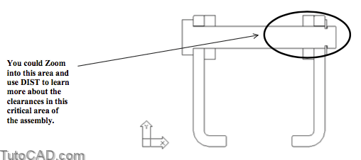
If the pin (above) was too large for the bracket then the interference SOLID would look like two cylindrical pipes shown below.
- the thickness of these pipes would represent how much material must be removed from either the pin or the bracket.

You could even Subtract the SOLID of interference from the bracket to enlarge the hole for a size-on-size fit
- although you would probably want to make the hole even larger than this to ensure a proper fit for assembly.
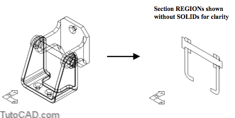
Use Section to draw a 2D section through a set of SOLIDs as a 2D REGION on the current layer.
- you can select one or more SOLID and a separate REGION is created for each SOLID object.
- these REGIONs can be used in 2D drawings or you can analyze them using other inquiry commands (e.g. Dist).
You can specify the plane for the desired section using 3 points (default) or you can use planes that are parallel to standard planes.
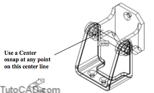
- for example, you could select a plane that is parallel to the ZX plane of the current UCS & passes through the center of the pin.
Command: SECTION↵
Select objects: ALL↵
Select objects: ↵
Specify first point on Section plane by [Object/Zaxis/View/XY/YZ/ZX/3points] <3points>: ZX↵
Specify a point on the ZX-plane <0,0,0>: CEN ↵
of (pick center osnap on pin)
Command:
PRACTICE ANALYZING SOLIDS
»1) Close the drawing from the previous exercise if it is open.
»2) Open the T304_10.dwg file in your personal folder.
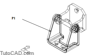
»3) Pick Tools + Inquiry + Mass Properties. Select the bracket SOLID near P1 and press <enter> to continue. Press <enter> until the Massprop command is terminated. What is the volume of this part?
»4) Pick Draw + Solids + Intereference. Follow the dialogue below to create a SOLID of interference for this assembly.
Command: INTERFERE↵
Select first set of solids:
Select objects: ALL↵
4 found
Select objects: ↵
Select second set of solids:
Select objects: ↵
No solids selected.
Comparing 4 solids with each other. Interfering solids: 2
Interfering pairs : 1
Create interference solids? [Yes/No] <N>: Y↵
Command:
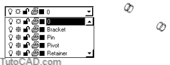
5) Freeze all layers except the current layer 0 (zero).
6) Erase the SOLID of interference.
7) Thaw the Bracket layer.
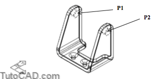
8) Pick Modify + Solids Editing + Offset Faces. Select the isolines of the two holes near P1 and P2 (you may have to Zoom In) and press <enter> to continue. Enter negative 0.010 as the offset distance and press <enter> twice to terminate Solidedit.
9) Thaw all layers.
10) Pick Draw + Solids + Interference. Use the command line history as a guide to see if the pin still interferes with the bracket.
Command: INTERFERE ↵
Select first set of solids:
Select objects: ALL↵
4 found
Select objects: ↵
Select second set of solids:
Select objects: ↵
No solids selected.
Comparing 4 solids with each other. Solids do not interfere.
Command:
Now the shaft fits in the holes in the bracket because you enlarged these holes.
11) Pick Draw + Solids + Section. Use the command line history as a guide to create a section through assembly of SOLIDs along the pin center line.
Command: SECTION↵
Select objects: ALL↵
4 found
Select objects: ↵
Specify first point on Section plane by [Object/Zaxis/View/XY/YZ/ZX/3points] <3points>: ZX↵
Specify a point on the ZX-plane <0,0,0>: (use Center osnap on any point on the pin center line)
Command:
» 12) Freeze all layers except the current layer 0 (zero).
» 13) Pick View + 3D Views + Front.
14) Save the changes to the drawing and Close the file.
More Practice
Mypart_1.dwg
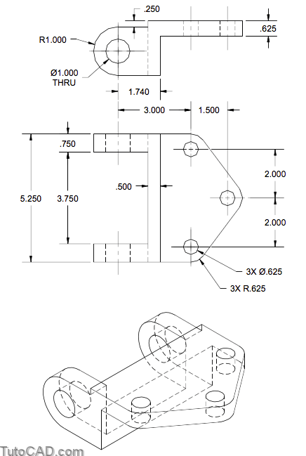
Create a solid model using the sketch & isometric view below and find the volume of this part (dimensions are in inches).
- save the file as Mypart_1.dwg in your personal folder.
Mypart_2.dwg
Create a solid model using the sketch & isometric view below and find the volume of this part (dimensions are in inches).
- save the file as Mypart_2.dwg in your personal folder.
