Tracking With Parallel & Extension OSNAPs
The Parallel osnap is powerful when combined with the other tools described earlier in this document.
- you can acquire Alignment points using the Parallel osnap to constrain the tracking vector parallel to the segment of interest.
- the Parallel osnap can avoid having to define a temporary UCS or create temporary construction objects (e.g. avoid Offset).
The Extension osnap (new in AutoCAD 2000) lets you Track along the extension of existing objects (even non-linear objects like ARCs).
- this can avoid having to create temporary construction objects (e.g. Lengthen existing LINEs) just to find the desired point.
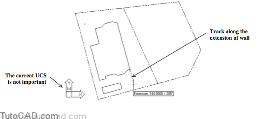
- for example, you could track along the extension of a foundation wall LINE when the current UCS is not aligned with this wall.
PRACTICE WITH PARALLEL AND EXTENSION OSNAPS
- Continue with the drawing from the last exercise(or Open the T204_4.dwg drawing in your personal folder).
- Verify that the following status bar buttons are On.
![]()
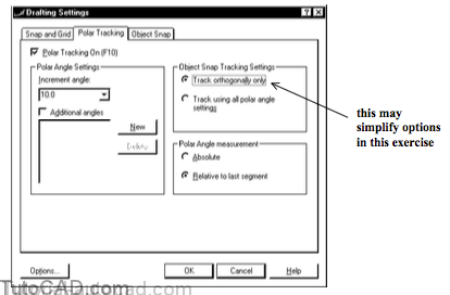
3) Right-click on the POLAR status bar button and select Settings from the Shortcut. Select Track orthogonally only and then select the Object Snap tab.
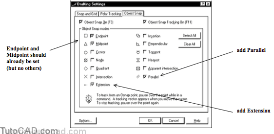
4) Add Extension & Parallel & pick the Snap and Grid tab.
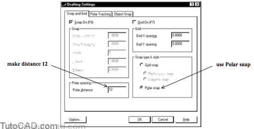
5) Your settings for Snap and Grid should still be as shown below (if not set them this way). Then pick OK.
6) Make LEGAL the current Layer.
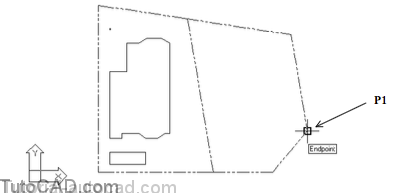
7) Pick Draw + Line & left-click on the Endpoint near P1.
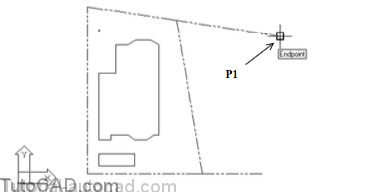
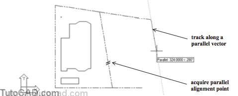
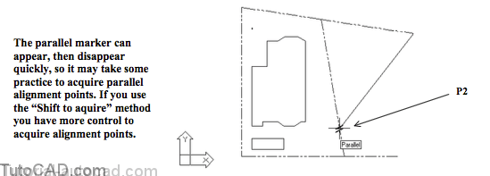
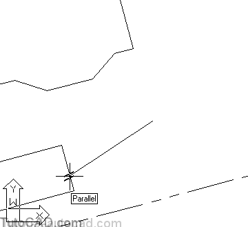
8) Move your crosshairs over the LINE near P2 to acquire a Parallel osnap as an Alignment point (do not left-click).
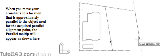
9) Move your crosshairs until you see the Parallel osnap marker on the Alignment point and a tooltip that says Parallel: 492.0000 < 280 then left-click to use this point.
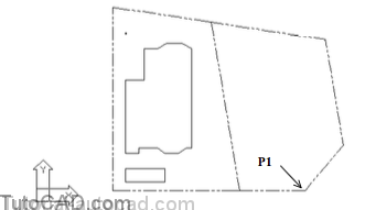
10) Then left-click to use an Endpoint osnap near P1 and press <enter> to complete Line.
11) Pick Format + Point Style and select the style shown below. Then pick OK.
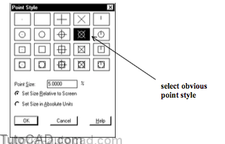
In the next step you will place a survey marker symbol using a POINT object and you will want it to be an obvious style.
12) Pick Draw + Point + Single Point and hold your crosshairs over the Endpoint osnap near P1 to acquire this as an Alignment point but do not left-click on it.
13) Move your crosshairs to the location shown below such that the tooltip says Extension: 120.0000 < 280 and then left-click to use that point.
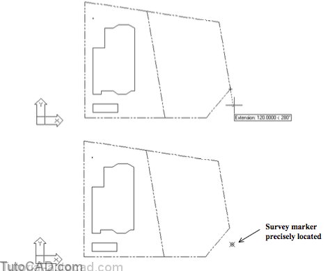
You could have used the Lengthen command on the LINE and then you could have created the POINT at the new Endpoint of the LINE
- but you would have to Trim the LINE back to the required length (which is more work than Tracking with Extension).
14) Pick Tools + New UCS + World to restore the WCS.
15) Pick View + 3D Views + Top to align your view to the WCS.

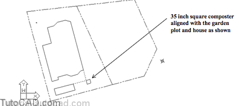
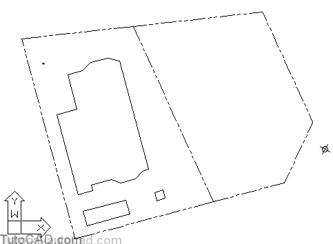
In the next few steps you will create a square that is 35 drawing units per side and aligned with the existing LINEs as shown below
- the size of the square is not a multiple of the current snap increment so you will use direct distance entry techniques.
16) Make FOUNDATION the current Layer again.
17) Pick View + Zoom + Window to zoom into a closer view of the area you will be working on.
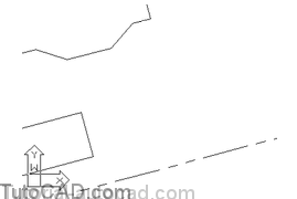
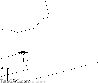
18) Pick Draw + Line and move your crosshairs over the Endpoint shown below to acquire it as an Alignment point but do not left-click to use it as an osnap point.
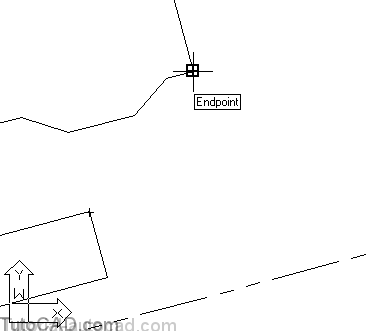
19) Move your crosshairs over the Endpoint shown below to acquire it as an Alignment point but do not left-click.
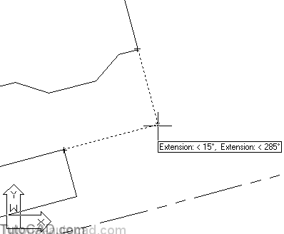
20) Move your crosshairs to the position shown below so the tooltip says Extension < 15, Extension: < 285 then left- click to use this point.
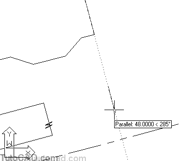
21) Hold your crosshairs over the Parallel osnap point shown below to acquire it as an Alignment point (do not left-click).
22) Move your crosshairs to a point shown below so the tooltip says Parallel and enter 35 as the distance at the keyboard.
23) Move your crosshairs until you see the Relative Polar tooltip appear in the 90 degree direction shown below and enter 35 as the distance at the keyboard.

24) Use a similar technique to create the other two edges of the square with direct distance entry and Relative Polar tracking vectors then press <enter> to complete Line.
25) Pick View + Zoom + Previous to see the entire drawing.
26) Save these changes to your drawing and Close the file.
More practice?
27) Add the outline of a sidewalk (aligned with the house) using LINEs. Do NOT change your UCS and do NOT use the Offset command. Draw LINEs directly using the drafting techniques that you learned in this document.
Still more practice?
28) Open the T204_5.dwg drawing in your personal folder.
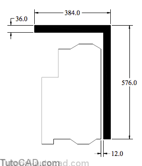
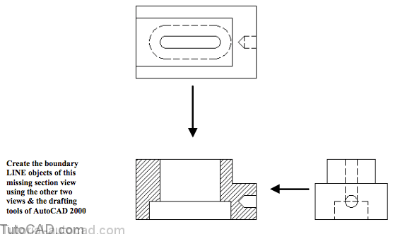
29) Complete the section view of the part shown below using ONLY the Line command.
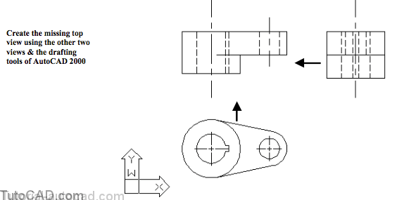
30) Open the T204_6.dwg drawing in your personal folder.
31) Create the missing top view using only the Line command.