Using Object Snaps Osnaps Effectively
When you use object snap overrides to supply points that relate to existing objects, they are in effect only for your next point.
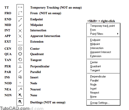
- you can type abbreviations of desired osnap overrides at the keyboard (the abbreviations are shown by each button below).
- you can also press & hold <shift> and then right-click in the drawing area to select an osnap override from a shortcut menu.
- or you can use an osnap button from the Object Snap toolbar & from the Object Snap flyout button on the Standard Toolbar.
You should use osnap overrides for the modes you do not use often and set running osnaps (see next page) for commonly used modes.
Running osnaps are automatically in effect when the OSNAP status bar button is On so this approach requires the least amount of effort.
- you will see object snap markers appear if you hold your cursor over an object when an appropriate osnap mode is set.
- press the <Tab> key (when you see any osnap marker) to cycle through other applicable osnap modes that are currently set.
- left-click when the desired osnap marker is displayed to use that point at the AutoCAD point prompt.
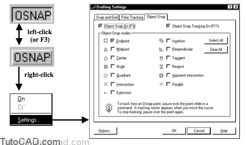
You can set the desired running osnap modes by selecting them on the Object Snap tab of Dsettings.
- a quick way to directly access this tab is to right-click on the OSNAP status bar button & pick Settings in the shortcut.
The OSNAP button will be Off if no running object snaps are set
- then if you left-click on OSNAP you will invoke Dsettings(because there are no running osnaps to turn on).
Set ONLY the running osnap modes that you use regularly.
- then you can cycle quickly through these set modes when you press the <Tab> key.
- you can add or remove running osnap modes transparently (while other commands are running).
Object Snaps (override and running) are affected by several settings that can be changed from the Drafting tab of Options.
- these settings (saved in your registry) include the AutoSnap Marker Size, the Aperture Size and AutoSnap Settings.
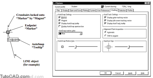
The Marker displays the current object snap location when you hold your crosshairs over the snap point of an object.
- you can adjust the marker size to suit your preferences (and your screen resolution) with the AutoSnap Marker Size slider.
When Magnet is checked your crosshairs jump to osnap points if your crosshairs are inside the Marker.
When Display AutoSnap Tooltip is checked the currently selected object snap is displayed in a tooltip.
Display AutoSnap aperture box is normally not checked so you do not see how large the current Aperture Size is on your screen.
- when you are experimenting with these tools it may help to temporarily display the aperture box.
- then you can experiment with Aperture Size (using the sliding adjustment) to find a setting that best suits your needs.
The AutoSnap marker color is Yellow by default and this is an obvious color with a Black screen background (default color).
- you might prefer a more obvious color (e.g. Blue) if you change your background screen color to White.
PRACTICE WITH OSNAPS
»1) Close the drawing from the previous exercise if it is open.
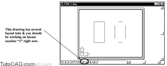
»2) Open the T204_1.dwg drawing in your personal folder.
»3) Make sure that the OSNAP status bar button is Off. (left-click on it if it is On).
![]()
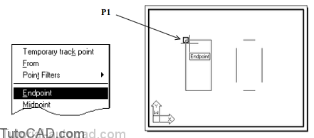
»4) Pick Draw + Line. Press & hold <Shift> while you right- click in the drawing area to invoke a shortcut then pick Endpoint. Hold your crosshairs near P1 and when the Endpoint marker & tooltip appear, left-click to use this point as the start of the LINE.
The Aperture size (see page 12) determines how close you must be to an object before an osnap marker & tooltip appear.
- this aperture box is normally invisible because Display AutoSnap aperture box is unchecked by default.
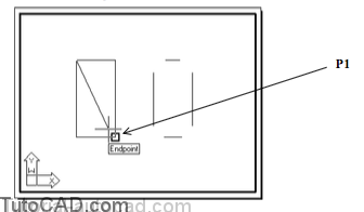
5) Press & hold <Shift> again while you right-click in the drawing area to invoke a shortcut then pick Endpoint. Hold your crosshairs near P1 and when the Endpoint marker & tooltip appear again, left-click to use this point as the end of the LINE segment. Press <enter> to terminate Line.
Using osnaps as overrides like this can be inefficient because an override is only good for the next point you pick.
- you must explicitly invoke the desired osnap mode every time you need another osnap point.
» 6) Right-click in the drawing area to invoke a shortcut and pick Repeat Line.
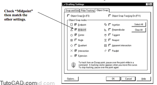
» 7) Right-click on the OSNAP status bar button to invoke a shortcut and pick Settings. Check the Midpoint mode and make sure the other modes are checked as shown then pick OK to continue using Line.
8) Left-click on the OSNAP status bar button to toggle this setting On.
![]()
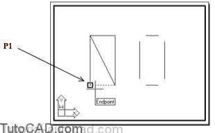
9) Move your crosshairs near the corner of the rectangle at P1 (but do not left-click yet) and repeatedly press the <Tab> key when you see any osnap tooltip appear.
Each time you press the <Tab> key you should notice a different combination of osnap marker & tooltip
- there may also be different objects highlighted as well.
You can use this technique to select the desired osnap when several running osnaps are set at the same time.
you may have to <Tab> several times to get to the desired mode if there are many objects nearby & you have many osnaps set.
- left-click to use the osnap marker currently displayed.
» 10) When the Midpoint osnap is invoked as shown below,left-click to use this as the start of the LINE.
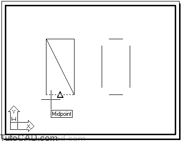
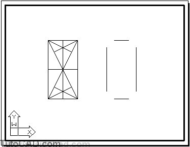
11) Use the techniques of your choice to create the new LINEs shown below with Midpoint, Endpoint (or Intersection) and Perpendicular osnap modes.
12) Pick Draw + Line. Hold your crosshairs near P1 then repeatedly press the <Tab> key when an osnap tooltip appears. Stop when you see an Intersect With tooltip as shown below.
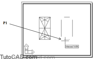
13) Move your crosshairs near P2 and left-click when you see the Intersection tooltip & marker appear as shown below.

LINEs (and other objects) do not have to actually cross for you to find a point of Intersection (where they would cross if extended).
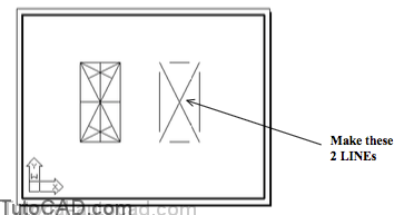
14) Use a similar technique to draw two LINEs between the intersection points (of LINEs that do not actually cross) as shown below.
Center, Quadrant Tangent Practice
15) Left-click on the 2 layout to make it the current layout.
![]()
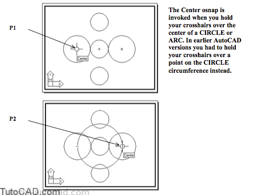
16) Pick Draw + Circle + 2 Points. Right-click on OSNAP to invoke a shortcut and pick Settings. Make sure that (at least) Center & Quadrant are checked then pick OK to continue. Invoke the Quadrant osnap shown near P1 then left-click to use this point as the first CIRCLE point.

17) Move your crosshairs near P2 to invoke the Quadrant osnap shown & left-click to use this as the second CIRCLE point.

18) Right-click in the drawing area to invoke a shortcut and select Repeat 2 Points. Move your crosshairs near the center of the CIRCLE at P1 to invoke a Center osnap and left-click to use this as the first CIRCLE point. Use a similar technique to supply the Center of the CIRCLE near P2.
19) Pick Draw + Line. Press & hold <Shift> then right-click in the drawing to invoke a shortcut and select Tangent. Hold your crosshairs near P3 to invoke the Tangent osnap shown. Left-click to use this as start point of the LINE.

You could use a Tangent running osnap if you did NOT already have Center or Quadrant running osnaps set.
20) Use a technique of your choice to complete 4 new LINEs such that they are Tangent to the CIRCLEs as shown.

Insert, Node & Nearest Practice
21) Left-click on the 3 layout to make it the current layout.
![]()
22) Pick Modify + Scale. Select the Plant block insert in the corner and press <enter> to continue. Right-click on OSNAP in the status bar to invoke a shortcut and select Settings. Check only Node & Insertion and pick OK to continue. Move your crosshairs near P1 to invoke the Insert osnap shown & left-click to use this as the base point. Then enter 1.5 at the keyboard in make this plant grow 50%.

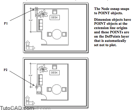
23) Pick Tools + Inquiry + Distance. Move your crosshairs near the extension origin of the dimension at P1 to invoke the Node osnap shown & left-click to use this as the first point. Use the same technique to snap to a Node osnap for the other origin point of this dimension near P2. The distance report should be 172 units (14 feet 4 inches).
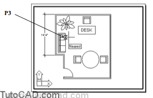
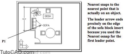
24) Pick Dimension + Leader. Press & hold <Shift> while you right-click in the drawing area to invoke a shortcut and select Nearest. Move your crosshairs along the outside edge of the sofa insert near P3 to invoke the Nearest osnap shown. Left-click to use this as the first point of the Leader.
25) Move your crosshairs near P1 and left-click to use this as the second leader point. Enter SOFA and press <enter> to terminate the command.
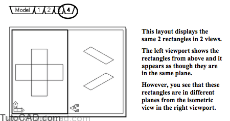
Apparent Intersection Practice
26) Left-click on the 4 layout to make this the current layout.
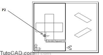
27) Pick Draw + Rectangle. Press & hold the <Shift> key while you right-click in the drawing area to invoke a shortcut and select Apparent Intersect. Hold your crosshairs over the point near P2 and left-click when you see the Extended Apparent Int tooltip shown.
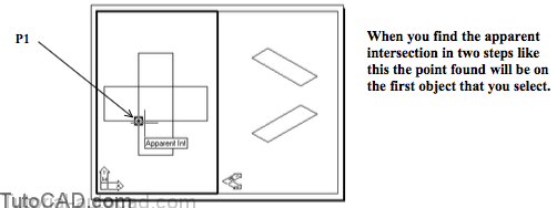
28) Move your crosshairs near P1 and left-click when you see the Apparent Int tooltip to use this as the first corner point.
29) Press & hold <Shift> while you right-click in the drawing area for a shortcut and select Apparent Intersect again. Move your crosshairs near P2 and left-click when you see the Apparent Int tooltip shown for the second corner point.
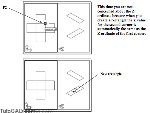
Can you do this?
30) Create another rectangle that appears to be the same as your last rectangle in the left view but this time create the rectangle in the same plane as the uppermost rectangle.
31) Save the changes to your drawing and Close the file.