How to use POLAR With Direct Distance Entry
Here is how to use polar direct distance entry in AutoCAD
You can use the POLAR tool in AutoCAD in the same way that you would use a T-square when you make drawings manually.
When POLAR is On in the status bar your next point can be constrained vertically or horizontally.
- hold your crosshairs approximately in a vertical direction from your last point to constrain your next point vertically.
- hold your crosshairs approximately in a horizontal direction from your last point to constrain your next point horizontally.
- otherwise your next point is not constrained (the next point is the exact location of your crosshairs when you left-click).
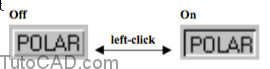
You can toggle the POLAR status bar button On or Off at any time by left-clicking on this button
- or press the F10 function key or check/uncheck Polar Tracking On on the Polar Tracking tab of Dsettings.
A quick way to get to the Polar Tracking tab of Dsettings is to right-click on the POLAR status bar button to invoke a shortcut
- then select Settings from the shortcut.
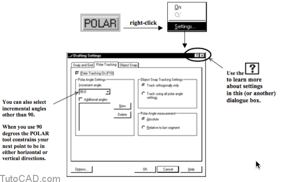
Polar tracking is a powerful feature with many settings to consider.
- to learn more on your own, click on the question mark box ( ?) in the upper right corner of the Dsettings dialogue box.
- then click near the desired setting on the Polar Tracking tab of the Dsettings dialogue box to learn more about that setting.
- you can use the What’s this? feature whenever you see a question mark button in a dialogue box.
Once you constrain your next point in the desired direction you can use direct distance entry to specify a distance in that direction.
- type the desired distance on the command line.
- when the Polar tooltip displays the desired angle press <enter> to use this precise distance & direction for the next point.
For example, to draw a vertical LINE that ends at 0.5 drawing units directly above the starting point you would
- invoke the Line command and supply the starting point.
Command: _line Specify first point: (pick starting point P1)
- type 0.5 at the keyboard, hold your crosshairs vertically above the starting point & press <enter> when the tooltip angle is 90.
Specify next point or [Undo]: 0.5 ↵
(press <enter> when the Polar tooltip angle is 90 degrees) Specify next point or [Undo]: ↵
Command:
Practice using POLAR with direct distance entry
- Close the drawing from the previous exercise.
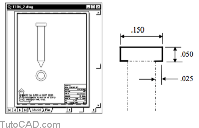
- Pick File + Open & select the T104_2.dwg drawing in your personal folder.
You will use POLAR with direct distance entry to complete the outline of a pin in this drawing.
- you will create 8 new LINE objects without having to explicitly type relative or absolute coordinates.

3- Verify that the OSNAP button is still On in the status bar.
![]()
4- Left-click on the POLAR status bar button (if it is Off) to toggle this tool On.
![]()
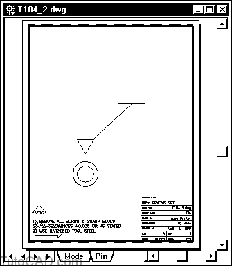
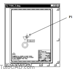
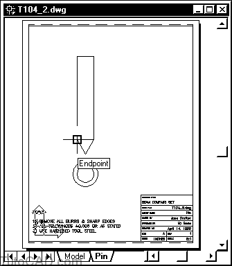
5- Pick Draw + Line and hold your crosshairs over the point shown below until you see the Endpoint osnap marker. Left-click to use this point.
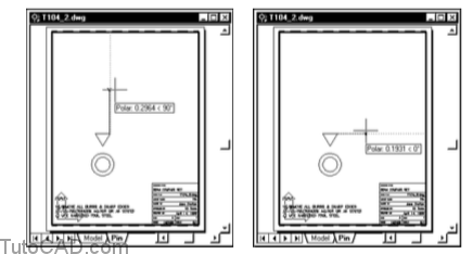
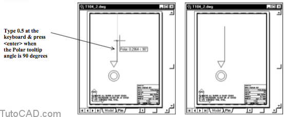
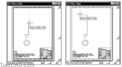
6- Move your crosshairs in a vertical direction above the last point.
When your Polar tooltip angle is 90 degrees type .5 at the keyboard and press <enter>.
Move your crosshairs to the left
and when the Polar tooltip angle is 180 degrees type .10 at the keyboard
and press <enter>.
So far you have created two new LINE objects but you have not entered any relative or absolute coordinates.
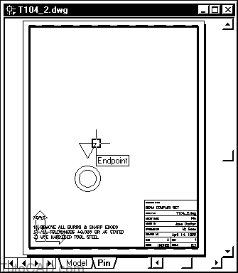
- you have an Endpoint running osnap set and OSNAP is On so you could snap to the starting point precisely with little effort.7- Hold your crosshairs over the point shown below and left-click when you see the Endpoint osnap tooltip. Then press <enter> to complete the Line command.
8- Add the remaining five LINE objects to model the side view for the head of this pin using the POLAR tool with direct distance entry.
An enlarged view of these 5 new LINE objects is also shown.