How to use Snap & Grid
Here is how to use the snap and grid tools in AutoCAD
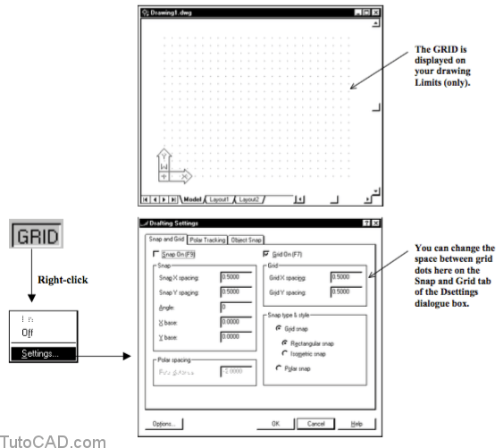
When you turn On the GRID in the status bar you will see an array of dots on your screen at a fixed spacing in the X and Y directions.
- you can use the GRID as a visual frame of reference and the dots in your GRID will not appear when you Plot.
- the GRID is displayed ONLY in the drawing Limits area.
- you may not see the GRID when you are zoomed out if the space between each dot is too small (too dense) to display.
- the GRID setting does NOT constrain your crosshair movement.
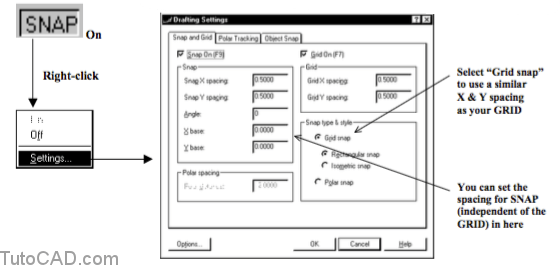
When you turn On the SNAP tool in the status bar your crosshairs are constrained to move in set increments.
The SNAP tool can be set to either Grid snap or Polar snap and the snap behavior is quite different for each snap type.
- when you select Grid snap your snap spacing is like the GRID. (you can use different X & Y spacing compared to the GRID)
- if you use Polar snap you can constrain your cursor to move in incremental distances relative to your last point.
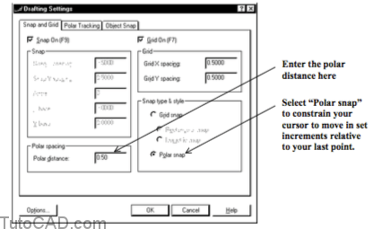
You must turn the POLAR tool On to use the Polar snap approach
- and the incremental angle can also be set to use angles other than 90 degrees on the Polar Tracking tab of Dsettings as well.
You can also set up SNAP and GRID to help sketch 2D isometric representations of 3D objects.
- select Grid snap as the Snap type & style and then select the Isometric snap radio button underneath.
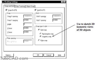
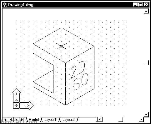
When you are in this mode you can toggle between Right, Left and Top iso planes by pressing and holding <Ctrl> while you press E.
It is more practical to create true 3D solid models compared to sketching them isometrically in 2D.
- then you can view your 3D models from an isometric viewing direction to create an isometric view.
Practice with this SNAP & GRID tutorial in AutoCAD
- 1- Close the drawing from your previous exercise.
- 2- Pick File + New and select the Start from Scratch button. Select English as the Default Settings and then pick OK.
- 3- Make sure SNAP and GRID are both Off in the status bar.
- 4- Move your crosshairs around and observe the coordinate read-out in the lower left corner on your screen.
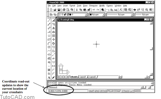
If your coordinate read-out does not change when you move your crosshairs then the coordinate display may be turned Off.
- you can double-click in the coordinate read-out to toggle the coordinate display On and Off.
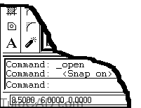
SNAP is Off right now so you can move your crosshairs to any location on-screen.
- the coordinate read-out will change with even slight movements of your mouse.
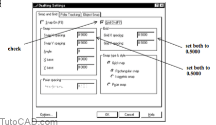
5- Right-click on the GRID status bar button to invoke a shortcut and select Settings to continue.
6- Check Grid On.
Make sure the Grid and Snap spacing for X and Y are all set to 0.5000
then pick OK.
7- Move your crosshairs & observe the coordinate read-out.
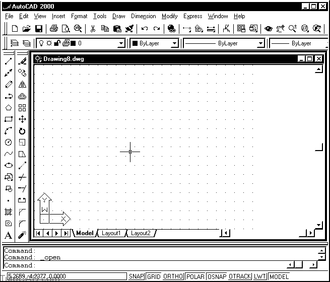
You see the GRID displayed on-screen but your crosshairs are not constrained to reside on these GRID dots.
8- Left-click on the SNAP button in the status bar to toggle this tool On. Then move your crosshairs around the screen and observe the coordinate read-out.
Now your crosshairs hop from snap point to snap point and the coordinate read-out changes in increments of 0.5000 units.
9- Pick Format + Drawing Limits.
Move your crosshairs until the read-out says 2.0000,1.0000,0.0000
then left-click to use this point as the lower left corner.
Move your crosshairs until the read-out says 10.0000,8.5000,0.0000
then left-click to use this point as the upper right corner.
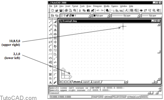
Now the GRID is displayed over a smaller area because you made your drawing limits smaller.
however, the SNAP tool is in effect even outside of these limits.
10- Right-click on the SNAP status bar button to invoke a shortcut and select Settings to continue.
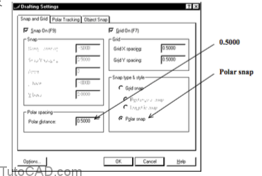
11- Select Polar snap as the Snap type & style
& enter 0.5000 as the Polar distance.
Select the Polar Tracking tab to continue.
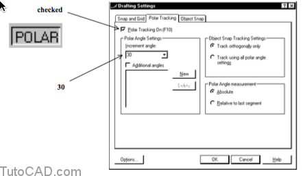
12- Make sure Polar Tacking On is checked.
Select 30 as the Increment Angle
and then pick OK to complete Dsettings.
Now you have set up SNAP to use the Polar snap approach and your crosshairs should increment at distances of 0.5000
- but you can also move your crosshairs in directions that are multiples of 30 degrees (instead of the default 90 degrees).
- this is like using a 30 / 60 triangle in manual drafting.
13- Pick Draw + Line and enter 3,3 as the coordinates for the start of the LINE.
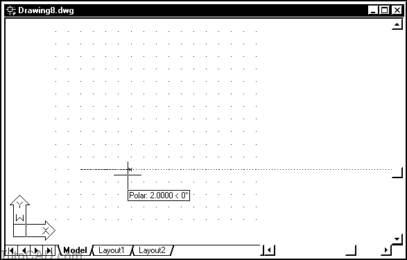
14- Move your crosshairs to the right to invoke the POLAR tool
and left-click when the tooltip says Polar 2.0000 < 0.
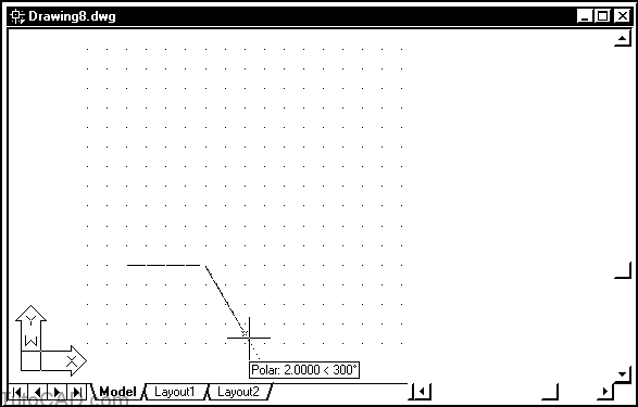
15- Move your crosshairs down and to the right to invoke the POLAR tool and left-click when the tooltip indicates Polar 2.0000 < 300.
You can snap to distances that are increments of 0.5 units relative to your last point as this is the Polar distance you set in step 11.
- and the direction is always a multiple of 30 degrees which was the increment angle you set in step 12.
- you can still use direct distance entry to override the snap distance while taking advantage of the Polar angle constraint.
16- Complete the outline of the shape shown below on your own using the Polar snap technique.
Press <enter> to complete the Line command when you get back to the starting point.
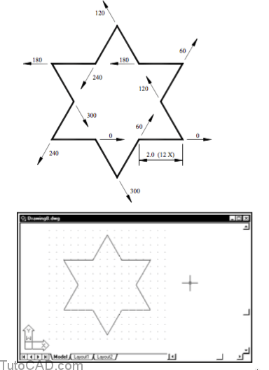
Compare the effort required to complete this shape in this exercise with the effort required using relative polar coordinates.
- this approach is much faster and requires very little typing at the keyboard once your Drafting Settings are set up.