Creating Lights & Defining Scenes
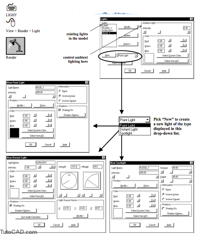
Use the Light command to create & edit the 4 light source types that include point, spot, distant & ambient lights.
Light Blocks
AutoCAD inserts a block at light locations to store lighting parameters as block attributes when you create new lights.
- the block is inserted on the current layer & attributes are on the ASHADE layer (which is automatically generated if required).
- there is no block required for ambient lighting as there is only one ambient light source.

The ASHADE layer is locked by default to help prevent accidental changes to these objects when you edit your model.
- you should make ASHADE the current layer before you create new lights so these blocks are inserted on a locked layer.
- use the Light command to modify existing lights (you should not use other AutoCAD commands directly on these blocks)
Changing Lights
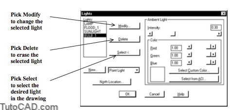
Lights defined in the current drawing are listed in the Lights list when you invoke the Light command.
- select the desired light in the list and pick Modify to change parameters (e.g. location or intensity) of the selected light.
- select the desired light to delete then pick Delete.
- pick Select to select a light block in the drawing (instead of selecting a light name in the list).
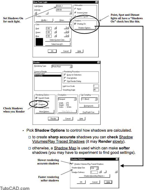
Shadows
A light will NOT cast a shadow unless Shadows On is checked for that specific light (i.e. in the Light dialogue box).
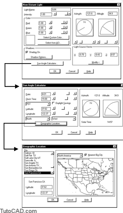
Distant Lights
A distant light has parallel rays so this is a good light type to simulate natural sunlight.
- use the Sun Angle Calculator to automatically set a direction for a given time, date & geographic location anywhere on earth
- or manually set the Azimuth & Altitude angles yourself.
- you can have more than one distant light in the same drawing.
Point Lights
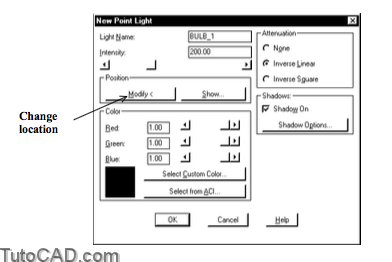
Use point lights to simulate light bulbs (& similar lights) for which the key parameter is the light location.
- pick the Modify button to specify a location on-screen for new or existing point lights.
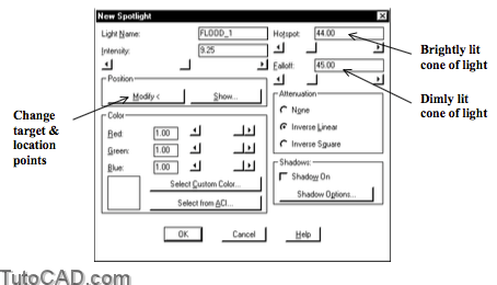
Spot Lights
Spot lights have a primary brightly lit cone of light with a secondary dimly lit cone up to a fall-off point where there is little or no light.
- pick Modify to specify a target point (center for the cones of light) and a light location point (apex for the cones of light).
- change the Hot Spot angle (brightly lit cone) using the slider or by typing an angle in the edit box.
- change the Falloff angle (dimly lit secondary cone of light) using the slider or by typing an angle in the edit box.
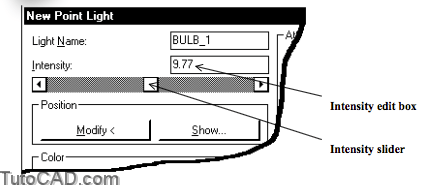
Intensity
Light intensity is an important factor but finding the best setting will require experimentation for each 3D model that you Render.
- each light type (point, distant, spot & ambient) has an intensity slider and edit box.
- change intensity settings gradually (for one light at a time) and verify the effects using Render after each small change.
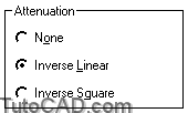
Attenuation
Light intensity diminishes as you move further from the source & you can simulate this effect using an appropriate attenuation setting.
- use None if you do not want intensity to change with distance.
- Inverse Linear decreases light intensity linearly with distance (double the distance and intensity is half)
- Inverse Square attenuates intensity by the distance squared (double the distance and intensity is one quarter).
- distant lights and ambient light do not have attenuation settings as there is no specific distance from the source.
Ambient Light
The ambient light in a scene is more important when you do not have very many other light sources of a relatively high intensity.
- ambient light has no location and no direction.
- it is simply an indication of background lighting.
- you control ambient light settings directly from the main Light dialogue box.
Light Color
Most light in nature and in artificially lit environments is white (or very close to being white).
- but you can simulate Light sources of any color by changing the relative amounts of Red, Green & Blue components.
- a light is white when all three components are equal.
The dialogue box for all four light types have a Color section.
- pick an AutoCAD Color Index (ACI) color & AutoCAD will compute appropriate components for Red, Green & Blue.

Use Scene to associate selected lights with a particular named view (if you have saved views by name) or the current view.

- pick New in the Scenes box to add a new scene.
- pick Modify in the Scenes box to change an existing scene.
- pick Delete in the Scenes box to delete a scene.
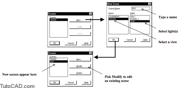
When you Render you can select a named Scene or simply render the current view.
- for example, you could have a DAY Scene (using only the SUN) and a NIGHT Scene (using only artificial lighting)
- then you could Render either the DAY or NIGHT Scene.

PRACTICE ADDING LIGHTS AND MAKING SCENES
1) Continue with the T306_2.dwg file (or Open T306_4.dwg in your personal folder if you did not do the previous exercise).
2) Make ASHADE the current Layer so new lights are inserted on this locked layer.
![]()
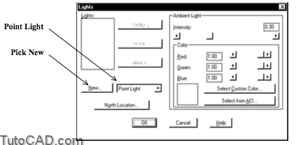
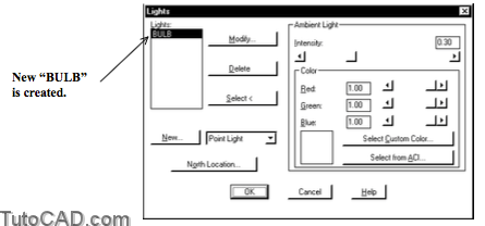
3) Pick View + Render + Light. Select Point Light in the drop-down list and pick the New button to continue.
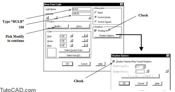
4) Type BULB as the Light Name. Check Shadows On then pick Shadow Options. Check Shadow Volumes/Ray Traced Shadows and pick OK to return to the New Point Light box. Type 100 as the intensity then pick the Modify button to continue.
5) Left-click once in the left isometric viewport to make it current. Press and hold <Shift> while you right-click in the drawing area to invoke a shortcut and select Node. Then left-click on the POINT near P1 to use the Node osnap shown for the location of the new light.
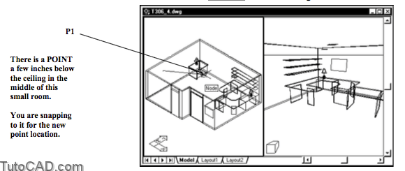
6) Pick OK to return and OK to terminate the Light command.
You can use any valid method to specify points for the location of new lights.
- POINT objects are inserted in this drawing to make it easier (using Node osnaps) for you in this exercise.
- you do NOT need a POINT object to insert a point light.
You used 100 for the intensity of this light bulb but this does NOT represent a 100 watt light bulb!
- intensity values are affected by attenuation settings & drawing extents & you must experiment to find acceptable results.
- the value of 100 is used because it produces acceptable results in this model.
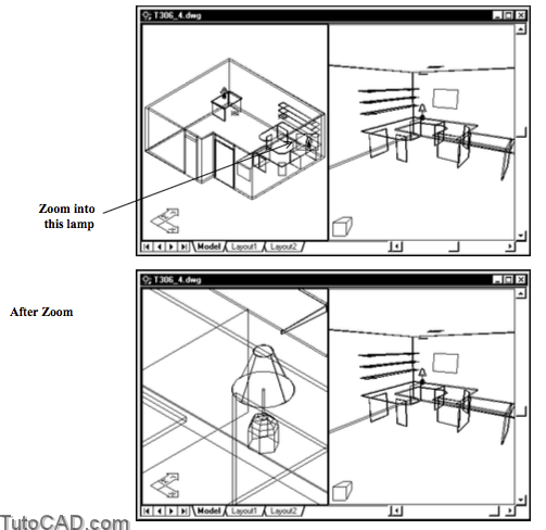
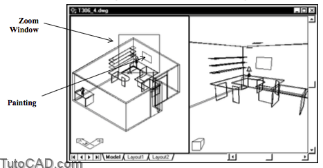
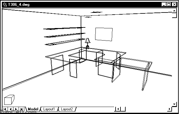
7) Pick View + Zoom + Window to zoom into a closer view of the lamp on the desk as shown below.
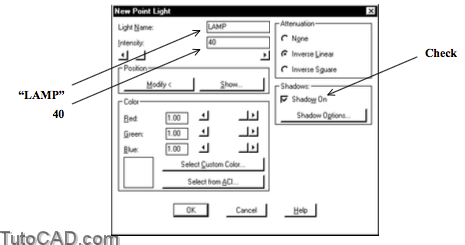
8) Pick View + Render + Light. Pick New when point light is selected. Type LAMP as the Light Name. Check Shadows On. Type 40 as the Intensity & pick Modify to continue.
9) Make sure the OSNAP status bar button is On. Invoke the Center osnap shown near P1 then left-click to use it as the light location & return to the New Point Light box.

10) Pick the Modify button again. Enter @0,0,1 as the new light location point. Pick OK to return then pick OK to terminate the Light command.
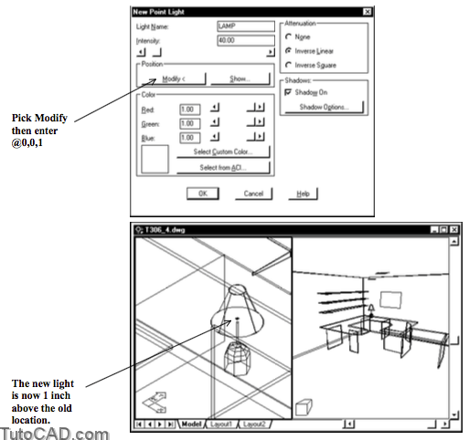
You can keep picking the Modify button to move the current light relative to the previous location.
- you used relative coordinates to move the light 1 inch above the previous location (at the top of the lamp stem).
This lamp model is for rendering purposes only (the lamp shade is suspended in mid air above the lamp stem).
- the lamp stem could have completely obscured all light coming from this light source because Shadows On is checked.
- it can be tricky to model light fixtures because you must permit the light to escape from the 3D model of the light fixture!
11) Pick View + 3D Views + SW Isometric.
12) Pick View + Zoom + Window & zoom into a closer view ofthe rectangle that will model a painting above the desk.
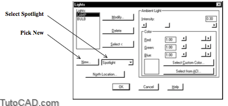
13) Pick View + Render + Light. This time select Spotlight as the light type and pick the New button to continue.
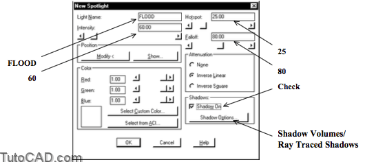
14) Type FLOOD as the Light Name and type 60 as the Intensity. Type 25 as the Hotspot and 80 as the Falloff. Check Shadows On. Pick Shadow Options and Check Shadow Volumes/Ray Traced Shadows. Then pick the Modify button to continue.
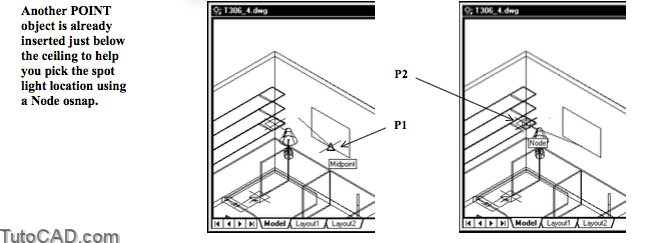
15) Press and hold <Shift> then right-click in the drawing area to invoke a shortcut and select Midpoint. Invoke the Midpoint osnap shown below near P1 and left-click to use this as the target point for the spotlight. Press and hold <Shift> then right-click in the drawing area to invoke a shortcut and select Node. Invoke the Node osnap shown below near P2 and left-click to use this as the location for the spotlight. Pick OK to return then pick OK again to complete the Light command.
16) Pick View + 3D Views + SE Isometric
17) Pick View + Viewports + New Viewports. Type Setup as the New Name for the current viewports. Pick OK.
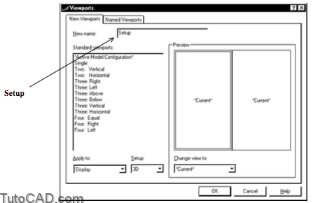
18) Left-click once in the right side viewport to make it the current viewport.
19) Pick View + Viewports + 1 Viewport.
It helps to save viewport configurations like the one that you used to define the lights in this drawing.
- if the view that you want to Render uses a perspective projection it will be difficult to pick points for lights.
- you could Render this view in full screen (one viewport) and you could return to the Setup viewports to add or edit lights.
20) Pick View + Render + Render. Select Photo Raytrace for the rendering type. Check the first three rendering options. Destination should be viewport. Pick the Render button.

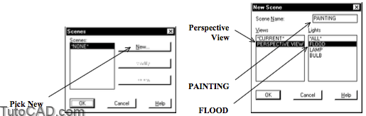
21) Pick View + Render + Scene. Pick the New button then select the PERSPECTIVE VIEW as the view and type PAINTING as the Scene Name. Select the FLOOD light then pick OK to return and OK to complete Scene.
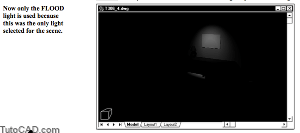
22) Pick View + Render + Render. Select PAINTING as the Scene then pick Render without making any other changes.
You have a few lights in the model but the photo realism comes from adding appropriate materials to surfaces.
- this is what you will learn how to do in the next section.
23) Save your changes to the current office drawing.
More practice?
24) Continue with the T306_3.dwg (or Open T306_5.dwg inyour personal folder if you did not do the previous exercise).
25) Make ASHADE the current Layer.
26) Pick View + Render + Light. Select Distant Light in the drop-down list and pick the New button.

27) Type SUN as the Light Name. Check Shadows On. Pick Shadow Options & check Shadow Volumes/Ray Traced Shadows then pick OK to return. Pick the Sun Angle Calculator button to continue.
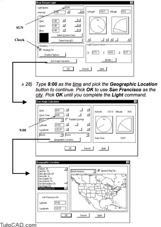
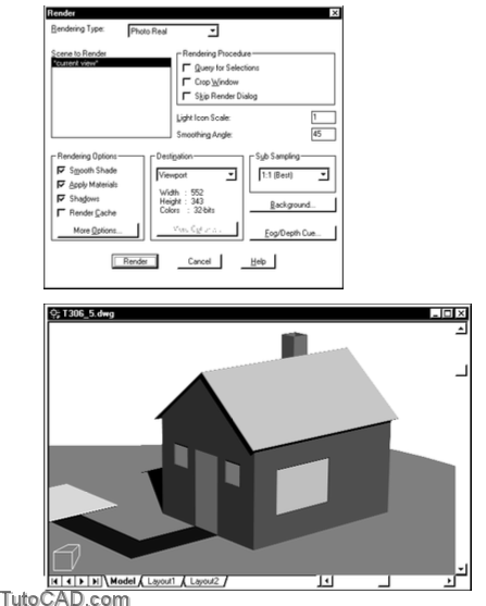
29) Pick View + Render + Render. Select Photo Real as the rendering type and check the first three rendering options. Destination should be viewport. Pick the Render button.
North is in the positive Y direction by default.
- in this model the front door faces South and you are presently simulating the morning sun.
» 30) Save your changes to the current drawing.