Rendering Overview in 3D drawing
Why Render?
Your ability to effectively communicate design concepts to others can be an important skill in any industry.
- traditional 2D drawings contain design details for construction
- but many people do not have the required skills, time or desire to understand the design information presented in drawing formats.
Full or reduced scale models and working prototypes are not as demanding for an audience to understand
- but they are also expensive and time consuming to make which cannot be justified in many cases.
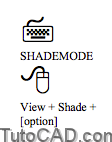
Shademode lets you quickly shade your models using the AutoCAD object colors of your model objects.
- shaded 3D models on-screen can be almost as effective (with minimal cost) as creating actual prototypes for presentations.
- you can even use 3dorbit to change viewing directions of your shaded model dynamically.
- your model (persistently) remains in the selected Shademode (select 2D or 3D Wireframe modes to exit Shaded modes).
For professional presentations you can assign realistic material properties to model surfaces & define lights in model scenes
- then Render the scenes as digital images to display on your screen, print or distribute electronically (e.g. on the internet).
Preparing models to Render involves many different commands and you must experiment with parameters to achieve the best results.
- most related commands can be invoked from the View + Render pulldown menu or the Render toolbar.
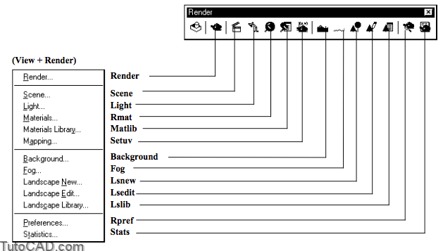
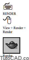
Render generates rendered images of scenes
Scene lets you assign specific lights to a named view
Light lets you create and control 4 different types of lights
Rmat lets you assign materials to surfaces
Matlib lets you import and manage predefined materials.
Setuv lets you map material bitmaps onto objects
Background lets you supply a background image
Fog adds fog effects which increase with distance
Lsnew, Lsedit & Lslib lets you add object bitmaps (e.g. trees).
Rpref controls rendering preferences (i.e. defaults)
Stats displays rendering statistics.
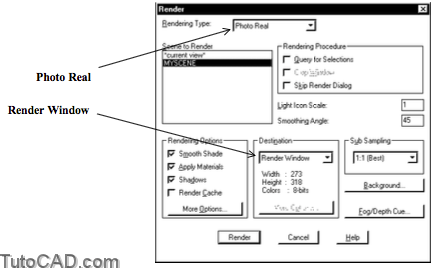
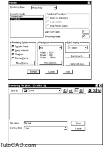
The Render command invokes a dialogue box that lets you adjust many different parameters before you create a rendered image.
- some of these parameters are presented in this section (other parameters are introduced later in this document).
- you normally do not invoke Render until AFTER you have prepared a 3D model for rendering.
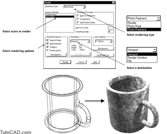
Rendering Type
The Photo Real & Photo Raytrace rendering types can produce the most realistic renderings & are required for some rendering options.
- you should experiment with both of these rendering types to achieve the best results for a given model.
- results using the Render rendering type are not much better than what you could achieve using Shademode in real time.
Scene To Render
You can simply render the current view or select a Scene that you have already set up in your model.
- Scenes let you experiment with different lighting effects.
- for example, you could make a night scene that uses artificial light sources (e.g. street lamps) & a day scene that uses sunlight.
Rendering Options
Rendering time will increase if you change settings to improve image quality or if you increase the number of surfaces in a model.
- you can pick the More Options button to change even more parameters & your options will depend on the rendering type.
- for example, you could improve rendered images by selecting an option for Anti-aliasing.
- settings that you can change by picking More Options are beyond the scope of this introduction to rendering.
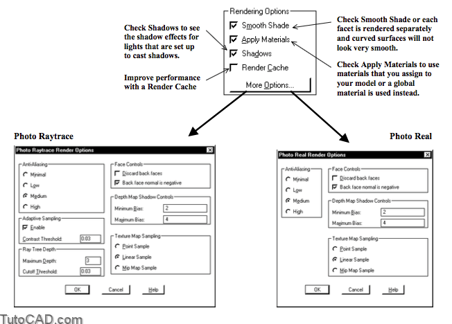
When Smooth Shade is checked the rendered image appears smooth even if the surface mesh in your model is not very smooth.
- faces that deviate from adjacent faces by more than the smoothing angle will render with an edge between each face.
- faces that deviate from adjacent faces by an angle less than the smoothing angle appear to be a continuous smooth surface.
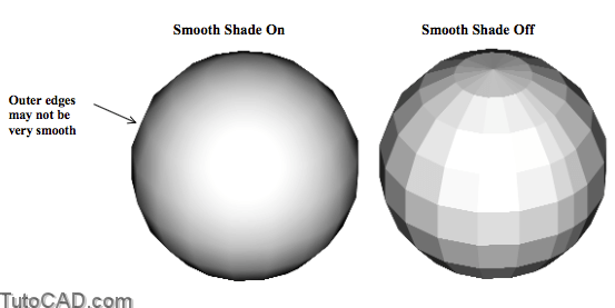
You can use relatively coarse meshes for faster render times and still have acceptable rendering quality
- but even if facets are smoothed using Smooth Shade the outer silhouette edges of curved surfaces may not look very smooth.
You can improve the smoothness of these outer edges by increasing VIEWRES and FACETRES.
- objects controlled by both VIEWRES and FACETRES are affected when you raise and lower the value of VIEWRES.
- only SOLID objects are affected when you raise and lower the value of FACETRES.
Use the default values (VIEWRES=100 and FACETRES=0.5) when you are experimenting with lighting & other effects
- then increase these values when you are ready to create final renderings (e.g. VIEWRES=1000 and FACETRES=2)
Destination
There are three destination choices for the rendered image
- Viewport
- Render Window
- File
Viewport sends the rendered image to the current viewport.
- use Redraw to return to the previous display.
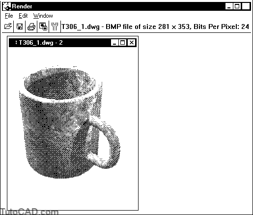
Render Window sends rendered images to a separate window where you can work with multiple images.
- for example, you can Print images using Windows printers or Save images to BMP (only) files.
- the Render Window is created when you invoke Render.
- pick File + Options in the Render Window before you invoke the Render command to specify resolution & color depth.
Use the File destination to send rendered images directly to a file.
- you can Render to BMP, PCX, Postscript, TIFF and TGAformats and your options will depend on the selected file type.
- you can set the resolution and many other parameters to optimize the image file by picking the More Options button.
If you Render an image to a file you can then use Imageattach to attach the file to drawings as an IMAGE object in AutoCAD.
- for example, you can attach the rendering of a part instead of an isometric hidden line viewport on a layout.
- your plot device must be able to Plot raster images if you want to use rendered images in your plot layouts.
Raster image files are only referenced by drawing files (they are not stored in the drawing file itself).
- you must be sure to archive raster images with your drawing files or these images will not appear when you open your drawings.
PRACTICE RENDERING A DRAWING THAT IS ALREADY SET UP TO RENDER
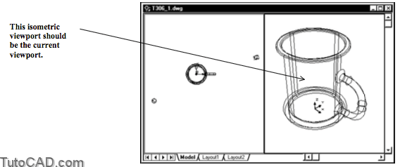
» 1) Launch AutoCAD (if required). Pick File + Open and select the T306_1.dwg drawing file in your personal folder. Close all other drawings (if other drawings are open).
» 2) Pick Tools + Run Script. Select the T306.scr script file in your personal folder and pick the Open button there to run this script. This sets several system variables to match the behavior illustrated in this manual.
3) Pick View + Shade + Gouraud Shaded. Then pick View + Shade + 3D Wireframe to return to the original mode.
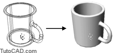
The cup is displayed in shades of the AutoCAD color (blue) that is assigned to this object (BYLAYER).
- it is as if you have a light above your shoulder but you cannot simulate other lighting conditions when you use Shademode.
- Shademode does not generate shadows and objects cannot be assigned realistic materials using this visualization tool.
4) Pick View + Render + Render. Select Photo Raytrace as the rendering type. Select MYSCENE as the scene to render. Smooth Shade, Apply Materials and Shadows should all be checked. Destination should be Viewport (the height & width on your system will probably be different). Then pick Render and wait for the viewport to change.
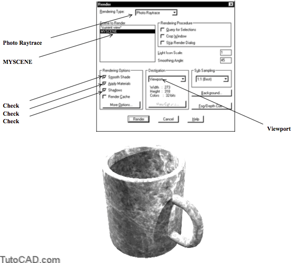
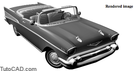
The cup looks more realistic in this rendered image compared to the Gouraud Shaded Shademode image in the previous step.
- the cup is a completely different color compared to the AutoCAD color of this object (it should look like green marble).
- the cup handle casts a shadow and you also see a shadow of the cup edge (inside the cup).
5) Pick View + Render + Render. This time select Render as the rendering type and the Shadows box will become unavailable. Pick Render.
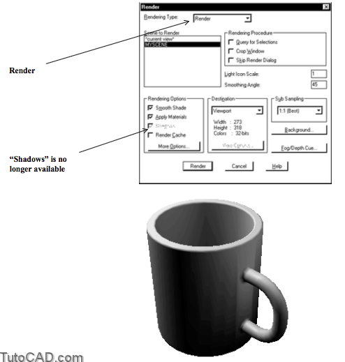
You lose realistic qualities of the previous rendered image when you use the Render rendering type.
- there are no shadows and the marble texture material (comes from a bitmap file) is no longer rendered onto the cup surfaces.
If you are satisfied with quality of the image currently on-screen then it would probably be simpler to use Shademode instead.
- use the Render command with Photo Real or Photo Raytrace rendering types when you need more realistic images.
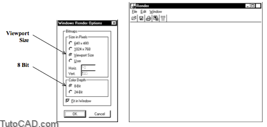
6) Select Render in your Windows task bar (at the bottom of your screen) to switch to the Render Window.
![]()
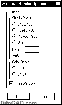
7) Pick File + Options. Select Viewport Size as the Size in Pixels to make the rendered image the same size (in pixels) as your current viewport. Select 8 Bit for the Color Depth. Pick OK.
8) Select AutoCAD in your Windows task bar (at the bottom of your screen) to switch back to the AutoCAD Window.
![]()
9) Pick View + Render + Render. This time select Photo Real as the rendering type and Render Window as the destination. Then pick the Render button.
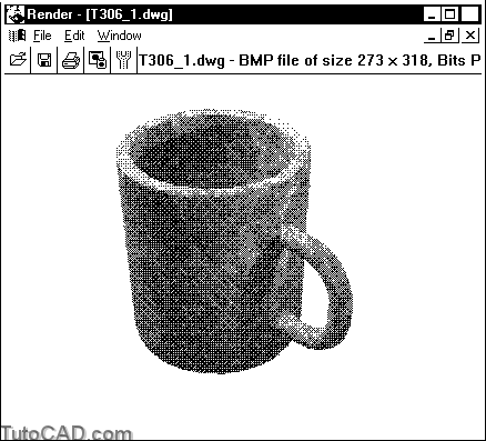
The image in your Render Window will be similar to the image displayed in the Viewport for the Photo Raytrace rendering type.
- Photo Raytrace and Photo Real rendering types yield similar results and you should experiment with both of these types.
You can use the Render Window as a scratch pad to temporarily store renderings while you experiment with various settings.
- this is a convenient place to compare images side-by-side (if there is more than one image they appear inside windows)
10) Pick File + Save in the Render Window. Type My Cup as the File name (*.bmp is automatic) and select your personal folder as the Folder. Then pick OK.
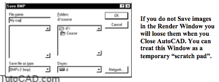
Now you could import this image file into other documents.
- for example, in a Word document you could pick Insert + Picture
+ From File and select this file to import the image into a doc file.
- use a White background in AutoCAD and your rendered images will have a white background (to match the paper in doc files).
More practice?
11) Select AutoCAD in your Windows task bar (at the bottom of your screen) to switch back to the AutoCAD Window.
![]()
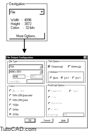
12) Pick View + Render + Render. Select Photo Real as the rendering type again. Select File as the Destination and pick the More Options button for Destination. Select TGA as the File Type,1024 x 768 as the resolution, 16 bits for the Color. Pick OK to return to continue.
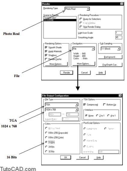
13) Pick the Render button. The Save in location should be your personal folder. Type My Cup as the File Name (*.tga is automatic). Pick the Save button to generate this image file.
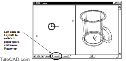
14) Left-click on the Layout1 tab to switch to paper space on this layout. Page Setup will automatically be invoked.
15) Select the Plot Device tab and select DesignJet 750.pc3 (or equivalent) as the Name for the plotter configuration. Select the Layout Settings tab to continue.
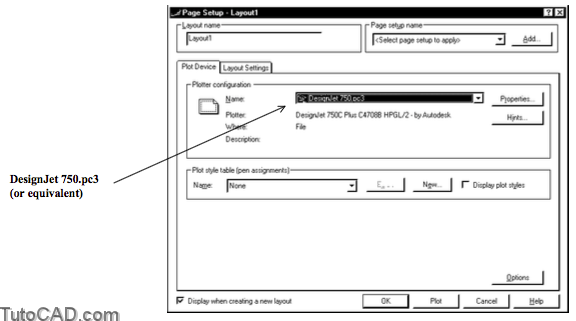
16) Select ANSI expand B (17.00 x 11.00 inches) as the paper size and make sure your other settings match those shown below. Then pick OK.

17) Pick Modify + Erase and select the viewport that is automatically created on this layout. Then press <enter> to delete this viewport.
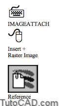
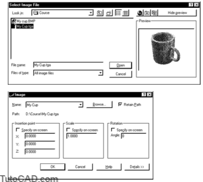
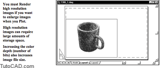
18) Pick Insert + Raster Image. Navigate to your personal folder and select My Cup.tga. Then pick Open. Uncheck all Specify on-screen boxes and pick OK to insert the rendered image in this layout.
19) Select the raster image to show the grips in each corner. Left-click on the upper right corner grip near P1 to make it hot then pick a point near P2 to Stretch the image. Press <Esc> twice to clear the grips.
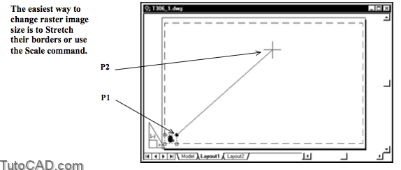
Many commands are available to work with images in AutoCAD.
- you can learn more about raster images using the AutoCAD Helputility by searching for topics related to the word IMAGE.
For example, you have already used the Imageattach command.
- Imageframe is another raster image command that lets you turn the frames of all raster images On or Off.
- turn frames Off when you Plot so the border of raster images do not appear in the plot.
- turn frames On when you need to select raster images (e.g. to Move or Scale images).
20) Close the current drawing without saving any changes.